jonescg's NEW electric racebike BUILD thread!

Wow, 700th post on the thread.

Finished the battery box ledges, so now it's secured inside the bike and can't leave in the event of a tumble.

ledges complete 001.jpg


The R clips stop it from moving up and down, while the pins stop it from rocking side to side. The steel supports stop the pack from rocking front to back. It also means you can remove the battery pack in under a minute - lift the tank cover, disconnect the signal plugs, pull the R-clips out, and hoist the pack up. Going to put a basic sling together for the pack using nylon webbing. It can stay on the bike.

Next job is to get a plug for the tank cover made. The carbon/glassing work can be done by someone else, but I will get some 3 mm MDF and start making the basic shape I want to cover the battery pack and auxiliary battery. Should be interesting...
 
I can get an R1 cover made in fiberglass for about $100.
Il go get 2 made if you want one.

DSC00001-2.jpg


DSC00002-2.jpg
 
Thanks for the offer Dan, but I'll get it made by Composite Components here in Perth since they've offered to do it for a similar fee. These are the guys who build all of the parts for the Entecho hoverpod, and I am trying to be strategic in my relationships with engineering firms over here; you never know when a sponsor might pop up.

I've been looking at getting the 12 V wiring loom planned out, and it looks like it won't be that hard to make it road-ready either. At the very least I need to find a couple of switch blocks for the bars. It would be nice to be able to ride it to the track :mrgreen:
 
2014 is going to be a good year. Voltron Evo will be completed in time to race - It simply has to!

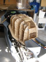
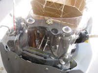
Today I have been busy getting a plug for the tank cover made. I cut some scaffolds up using MDF and lay them over the battery pack while it was in place. Likewise I used the battery pack as a guide for the L-R supports so I know the cover will clear the pack. The battery was surprisingly easy to lift straight out. I then made the other tank cover profiles for the sides and started to wrap it in jute cord with PVA glue holding it in place. I want to get it to a point where I can pour expanding foam into the vacant space and let it fill up the voids so I can then cut it back to the exact shape I want. I can use bog to get the surfaces right and once done, take it to Composite Components to have a mould made. The final product might even be made from Carbon!

Tank cover plug making.jpg

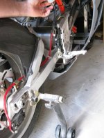
I have picked up a few of the last bits and pieces to make this thing roll. The new front wheel arrived on the 31st and the rear brake line is in the post office waiting for me to collect them. I'm missing a spacer on the front wheel, so it's just there for convenience right now.

Front wheel from Taiwan.jpg

The rear brake calliper I ordered of ebay arrived and the pistons are in good shape. I will give it a bit of a clean up, but the seals look good enough for me to leave them there. Same for the front callipers, but they are probably in pretty good shape.

Brembo rear brake.jpg

While at the wreckers I picked up a couple of switchblocks for the handlebars. While the rules state I need a kill switch and a horn, I figured it's not much trouble to wire them up with turn signals, brakes and lights, just leave these bits vacant on race day. So I've sketched out a dozen proto-looms for the 12 V wiring. Man this stuff is a PITA. Still, I'm hoping for two full looms which can be installed after the bike has been fully assembled. One for the instrument panel and controller inputs and the other for the lights and horn etc.

Switchblocks on bars.jpg

I think I might have the controller manage precharge and contactor closure, and have the safety button simply cut power to the controller provided this is safe to do.
 
Some more progress to report!

The rear brake line I had ordered was a smidge too long, so I got it shortened and now it fits great:
Rear brakes done.jpg

The tank cover plug has been slowly taking shape too. I was mixing up the bog as quick as I could only to have it set after barely two or three scrapes with the applicator. WTF? I read the instructions and they said it had a working time of 2-3 min... at 23 degrees C :lol: Unlike the 38'C inside my shed.

View attachment 2

Anyway, I would make the bog in the mornings and sand in the evenings. So far it's looking pretty good. Once I have all of the minor imperfections smoothed over I will take it to Composite Components and get them to make up a two part mould, and eventually a complete tank cover. I have a few options for securing it to the bike too. I will probably hollow out a channel so it clears the top tripleclamp, but the main fixings will be under the seat.

View attachment 1

Tank cover plug 002.jpg

It looks big, but you don't notice it when you're on the bike. Still allows for a comfortable tuck and plenty of sphinctoral puckering-knee-clenching strength where it's needed :D

I will soon have to pull the whole bike apart to remove the motor and get some drive sprockets made it. Who'd have thought that 44.5 mm output shafts were not commonly mounted to sprockets :roll: While everything is out I can clean the frame up and get it rust-primed and painted. I want it to be ready to display at Electrikhana (March 8th, RAC Driving Centre), batteries not included :(
 
After standing back and measuring up the size of the tank, I worked out that the plug is at least 40 mm too tall. Now was the time to correct it, so out with the angle grinder and handsaw... After a bit of chopping and hacking, and some 40 grit sandpaper I managed to shave it down to a more respectable size and shape.

Shorter tank plug 002.jpg

View attachment 1

Shorter tank plug 004.jpg

I'm hoping Glen from Composite Components can work his magic on this plug once it's done. I'm running short on time as well as money..
 
Hey everyone,

I have some exciting and terrifying news. Katherine is pregnant! Yes, we're expecting a baby to change our lives forever in early October. Terrifying because I don't have job, but that can change any minute.

It also means that Voltron Evo will no longer be the first recipient of what little I earn. That's going to have to go towards baby supplies and accessories. Granted we're going to borrow a bunch of baby stuff to save some money, but we are probably going to have to move somewhere slightly bigger with more distance between us and the neighbours. Ideally cheaper too. My angle grinder is pretty annoying, but only for a few minutes a day. Not all day... and night.

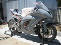
So I thought I might put some photos up of the progress to date, and list everything that needs to be done.

Voltron Evo Wheels on small.jpg

Voltron Evo RHS front.jpg

Voltron Evo RHS rear.jpg

In order of most pressing -

1. Get the fibreglass fairings repaired and tank cover made. This means paying a firm $150 to paint the plug in two-pack urethane paint and polish to a glassy finish. Then I will take it to Glen and get a mould and final part made. I will get KiM (AussieJester) to join the cuts I have made to the fairings so it fits around the bike.

2. Get the frame painted. I will just go with an acrylic paint once the rust-proofing primer has been applied. The fairings don't need to be painted, but the frame will only continue to rust if I don't get onto this.

3. While the frame is apart, I can take the motor down to WA Gears and get a couple of front sprockets splined. Danny Ripperton has kindly offered to make me an alloy rear sprocket, but I can also buy a Ducati 44 tooth rear which would be pretty close to an ideal ratio (17:44, top speed of 220 km/h or so). An RK chain is about $250 :(

4. Source and install a radiator for the bike. I don't have a lot of room, but any liquid cooled sports bike is bound to work in this case. As long as the wheel doesn't flex into the radiator under hard braking, I can make it work. The motor's continuous power is rated to 75 kW at 55'C coolant. The inverter can handle 90'C coolant - so I am confident about putting them on the same loop. I will also need a 12 lpm pump rated to 110'C for pumping coolant around the bike.

5. Place an order for ~540 LiPo cells about 5 weeks before I need them. This is about $6500. I can build the packs pretty quickly once they arrive - perhaps a week's work.

6. Place an order for a PM150DZ inverter. This is about $9000, however Brett is open to a rent-to-own arrangement to get me on track sooner.

7. Wire up the 12 V loom. This is pretty straight forward and affordable, but I will need to have the bike re-assembled to do it properly. I'll have it so disconnecting any component is easy. Things like the throttle, motor sensor wires, ignition start, precharge and ON features through the inverter... all needs some thought but nothing too crazy. I might start looming this out now.

So there you go. If I started a kickstarter/indegogo do you think there would be much support? I have no perks to offer except taking the finished product for a ride...

Interesting times ahead.
 
Congratulations Chris.

Oh indeed how life will never be the same again...

All for the better though mate. Fatherhood is fantastic. Good luck.

D
 
Congratulations on the family news!!!

As for the Kickstarter/Indiegogo I do think it is possible but it will be some work.
Your numbers add up to around 16,500 AUD however realistically you need around $20,000 to finish everything up and get it to the races. Transport costs, entry fees and consumables.

Indiegogo will let you do a fixed funding model or a keep any money donated. Kickstarter only does the fixed campaign.

If you want the best out of the campaign you need to offer incentives people want but affordable to deliver.
  • Off the top of my head.
  • Bumper Stickers $10
  • T Shirt $20
  • Pit pass (one race) $100
  • Pit pass (season) $400
  • Pit Crew member $400 (max 5?)
  • Advertising on bike (small) $500 (max 10)
  • Advertising on bike (large) $1000 (max 3)
  • Test Ride (x laps on a track day, must supply own safety gear) $2000 (Max 2)
  • Sponsor logo on team shirts $1000 (max 2)
  • Sponsor caps used by team $2000 (max 1)
  • Sponsor acknowledged by team during interviews and award ceremonies $2000 (max 4)


Also you have to promote the campaign like crazy... get it mentioned everywhere, all you facebook, google+, twitter and all others.
 
You're right, that does sound like a lot of effort. And it would take as much time as I could spend working... :lol: Still, I might look into it once things settle down a bit. The life of a volunteer can be tiresome - I am busy organising Electrikhana, leading the WA Electric Highways project, getting new brochures made for the AEVA and updating the AEVA website so corporate members can feel loved.

However I have got a project for Nechaus. Will PM you in a minute mate.

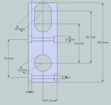
I need to get some proper fairing mounts made for the frame. I was using 32 mm pipe clamps which worked pretty well, but not good enough. They need two points of support, so I have devised the following half-clamps.

View attachment 2
View attachment 1
Fairing support dimensions.jpg

I'd need four of them all up. The fairings will then M6 bolt onto the lowest hole, and be held out by a 12 mm OD tube roughly 30 mm long. I can't get a 'waterproof' Sketchup image suitable for converting to a 3D Printer format, but with a bit of AutoCADing I reckon it should be pretty easy.
 
jonescg said:
Hey everyone,

I have some exciting and terrifying news. Katherine is pregnant! Yes, we're expecting a baby to change our lives forever in early October.

If I started a kickstarter/indegogo do you think there would be much support? .

So, is that Kickstarter to fund the bike ...or the baby ! :lol:

PS: enjoy the build whils you have the spare time....kids / family soon soak up much of that previously spare time.
..Oh, and bike racing is no pass time for a parent of a young family ! :cry:
 
Well heres my contribution to the Voltron objective.
Causing my CNC spindle to make 2 million 160,000 revolutions was the least I could do after failing to secure an $18k desperation loan that Chris could chain himself to for the next 5 years.
A 44tooth rear sprocket made from finest German 7075 T6 grade aluminium.
DSC00004_zps0db4b99f.jpg
 
Looking good there Dan! I gather the teeth are yet to be profiled? I hope to have the plug ready for mould-making in the next week.
 
Teeth are profiled. My tooth tips are broader than bought sprockets as they are stronger and longer wearing.
I will post a drawing showing the link approach and departure path.
 
That's a nice looking sprocket, nice job!
 
RIPPERTON said:
file.php

Are the brake lines dual all the way from the master cylinder ?
If theres a single line from MS to lower triple clamp it will cause a restriction and slow down reaction time (not joking)

That might be the case in theory but it certainly isn't the case in practice.
 
The tip radius (8mm) is slightly less than the roller path (10.775) meaning I can have the maximum volume of aluminium in this high stress zone without contacting the roller during approach and departure causing it to spin (wear).
Also the radius inversion point (red pointer) is on the line that runs between the 2 roller centers eliminating any ramping effect caused by designs that have pointed teeth.
The only way to draw sprocket teeth is with a parametric sketching system not found in AutoCAD but in Inventor 3D modeling program.
All AutoCAD does is 2D sketching, it doesnt do 3D with half the speed that Inventor does. Inventor is strictly 3D oriented but all solid objects have to start with a 2D sketch yet Inventors sketching tool is more powerfull than AutoCADs.

TOOTHPROFILE_zpsa00762ef.jpg
 
Back
Top