Kepler Friction drive comes of age.

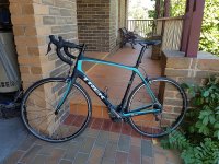
Decided for no real good reason that I needed a new road bike. Not being one to do things by half, I went out and purchased a new Trek Project One Domane SLR7 disc. Arrives in a month from the US as Project One bikes are custom assembled to the purchasers specification.

Trek7.JPG

This meant I needed to sell current Trek 2015 Domane 5.9. to help fund this new purchase. Now this is nice bike and was looking for a very reasonable $3,000. Not a bite. Dropped it to $2,500. Still not a bite. No way was I going to let a bike like this with the latest Ultegra DI2 go for such a ridiculous price, so it got me thinking, can I convert this bike to use my friction drive and then sell off my current friction drive road bike as a complete package.

Trek8.jpg

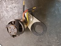
I had a bit of down time while I wait for the new locking plates to come back from the laser cutters so I decided to see if I could come up with a mount to suit the Trek's ultra wide BB90 bottom bracket.

The drive side bearing on a BB90 protrudes out from the bottom bracket but it does give you a bit of surface area to clamp too. Also with the bearing pressed into bottom bracket, it gave the clamping area quite a bit of crush strength.

Trek2.jpg

Trek1.jpg

i also wanted to keep most of the standard drive mechanic parts and modify as little of drive design as little as possible. Turned out better then I had hoped with the mounting position being very rigid plus the added bonus of being easily adjustable.

Trek3.jpg

Trek4.jpg

View attachment 3

Trek9.JPG

I am really pumped about converting this bike to use my friction drive. The bike was originally custom fitted to me and is such a comfortable ride. This bike will become my daily commuter with the new bike being my weekend bike.

Could this be the first ebike fitted with an Ultegra DI2 groupset. :)
 
Kepler said:
I believe the vesc can be activated with a direct on / off signal. Waiting on some additional information on to set this up.

I think this is close to what we need, but I am way over my head on the software explanations.

http://vedder.se/2015/08/vesc-writing-custom-applications/
 
I thought that too but this is an example of a custom App. The way i understand it Vesc, has the Apps we need already written and selectable within the BLDC tool.

Looking at the custom apps, it looks to be ready to use a hall throttle straight out of the box into the ADC input.

I am still to try all this but the pieces are coming together for me now.

Firstly forget about the PPM input that you have been using with the servo tester. We need to use the ADC port on the Vesc. This port is marked P3 on the board and with a magnifier you can read what each individual pin is on the back.

With regards to setup in BLDC tools, you first need to go to the App Configuration tab and read the configuration. Next select ADC. You will also need to reboot the controller once you do this. Once this is done, hit the Write button to send it to the controller.

Vesc1.JPG

Next you need the set up ADC peramiters.
Read the configuration to populate the default configuration. The default configuration looks like it is ready to accept a hall throttle input based on the minimum and maximum voltages. Select "Current" in the control mode section. I think this will suit our application but I need to better understand what the other option will do for us.

If you want to use a 10K pot or voltage divider rather then a hall throttle, I believe you will need to set to minimum voltage to 0.0V and maximum to 3.0V

Vesc2.JPG

Also worth noting that once you plug in your throttle, your can select the display an visually see what your voltage input is doing before you load up he controller by connecting your motor.

In regards to the actual connection, This is what I plan to try first. I think this is all we need but if I have missed something, I would appreciate someone more experienced with the Vesc controller to chime in

View attachment 1

This should give you simple on off control of your motor


This should give you variable current control of you motor

As I said before, I would appreciate someone with good Vesc experience to chime in and confirm the above is correct or if we need to change something.
 
A potentiometer has 3 pins. You connect it as this: //3V from Vesc// //VESC ADC input// //Ground//
By turning the pot (10kOhm for example works fine) the middle pin outputs 0-3V.

Nonetheless you better google a bit and wrapp your head around these things. Search for "potentiometer as a voltage divider".

Also make yourself familiar with the VESCs BLDC Tool. Especially the horizontal tab "App Configuration" which you can set to "ADC". Then you will see another vertical tab called "ADC" where you can tell your VESC how to utilisze your incoming 0-5V signal. You can find which pin is ADC by looking at the bottom of your VESC or you take a look on Benjamin webpage. Everything is explained there.

For further information on get on Benjamin Vedders youtube channel aswell. On youtube you can also find tutorials by "ESk8 Support" and others on how to properly set up your Vesc via BLDC Tool. You shouldn't mess things up here and follow instructions of someone understanding the matter properly.

Just take some time and search on google for forum threads concerning VESC usage and have fun. It's a really great device Benjamin developed for us to enjoy! :)

edit: Kepler you pretty much nailed it! If your Hall-sensor-throttle outputs any kind of an analog signal between 0-3V you can use it nicely. Just set your min and max Voltage to match your throttles output range et voilà!
Woops, just found out that ADC pins max Voltage is 3V. One should keep that in mind! I totally missed out on that before... Edited my post adequately. Sorry
 
Is the ADC_EXT pin max voltage 3.0V or 3.3V? Looking at the diagram below, with the 10K pot turned all the way to zero ohms, you would end up with 3.3V on the ADC_EXT pin as far as I can see. Will more then 3V damage the Vesc?
 

Attachments

  • Vesc6.JPG
    Vesc6.JPG
    43.2 KB · Views: 3,722
Kepler,

Not doing this by half is the biggest understatement I've ever read from you. Amazing fellow and a joy to read.

ATB,

Tom
 
Best news yet for my build, MAC OSX version for VESC setup. Perfect!
 
Decided to approach the Vesc throttle on/off button the same way I approached the standard ebike controller a few pages back as the input through the ADC_EXT is the same as an ebike controller except at a lower voltage. This approach uses a simple voltage divider with an added 1000uf capacitor to bleed down the voltage to the ADC_EXT pin for a nice soft spin down. Not sure if there is a parameter in the BLDC tool to handle this ramp down but for now analog will have to do.

View attachment 1

20161229_130102.jpg

So In the BLDC tool, chose the ADC App and set the minimum and maximum voltage to match the output of my voltage divider interface. The display feature within the BLDC tool showed exactly what the voltage input was. After all that, it was really straight forward with the button throttle working perfectly.

Now to decide what is the best control mode for the drive. i am thinking Current mode will be best but i will see.

Bench testing complete. Time to get it on the bike.

In the diagram below, I have adjusted the resistors to provide 1.0V in the off position and 3.0V at the on position. Min and Max voltage in the BLDC tool will need to be set the same of course.


[youtube]8Yr6NrswPDE[/youtube]

Thanks payder for putting me on the right track. :)
 
New build is coming along nicely. The drive mech is done and dusted. Just to be clear, this is a one off specifically for this bike. Not too many road bike use a BB90 so I don't think it is worth taking any further then a one off. Good thing is 90% of the drive is the standard setup. Only the clamping method is custom.

This bike will use a 230 kv 50mm motor. Controller will be a Vesc using FOC and will be a 10S 36V setup. I will be using a dual throttle button setup on this bike giving me 2 levels of assist. One ofthe great features of the Vesc is that it can be run in "Current Mode". This means the buttons will either give 50% current or 100% with no speed limiting. If "Duty Cycle Mode" was use as with a normal controller, 50% duty cycle would mean half the speed which is not what I want on a road bike.
 

Attachments

  • 20170217_164706.jpg
    20170217_164706.jpg
    151.4 KB · Views: 3,584
  • Friction Drive 2 button activation wiring diagram.JPG
    Friction Drive 2 button activation wiring diagram.JPG
    77.3 KB · Views: 3,584
Also trialing the installation of adhesive grip tape on the mounting bracket rather then using the anti rotation arm.

So far, this simple change is working better then expected with no movement of the drive on the bottom bracket even with the heavier 63mm motor. have only done about 10km of testing so far but it is looking promising. Got my regular 90km ride tomorrow so that will give me a clear picture if this change is a keeper.

This change drops the parts count and makes set up a little quicker. If successful, this design will be the production model. So close now :) .
 

Attachments

  • 20170217_123405.jpg
    20170217_123405.jpg
    105.8 KB · Views: 3,583
This throttle is still giving me fits.

I wired up the simple on/off switch as such

Vesc4.JPG

The problem is that the ADC voltage reading with the switch off is erratic, bouncing from 0-2.5+ volts. When the switch is on it is bouncing between 3.1 and 3.3, but when I turn the switch off the motor does not always disengage (not good!). There seems to be interference somewhere, not sure how the ADC voltage reading could be so unstable?
 
mhaskell said:
This throttle is still giving me fits.

I wired up the simple on/off switch as such


The problem is that the ADC voltage reading with the switch off is erratic, bouncing from 0-2.5+ volts. When the switch is on it is bouncing between 3.1 and 3.3, but when I turn the switch off the motor does not always disengage (not good!). There seems to be interference somewhere, not sure how the ADC voltage reading could be so unstable?


thats because the pin goes high when you press the button, but then FLOATS when you release the button. You need to pull it to ground so that it really is 0v with the button closed. thats why a voltage divider is used, instead of just a resistor.
 
Kepler said:
Also trialing the installation of adhesive grip tape on the mounting bracket rather then using the anti rotation arm.

So far, this simple change is working better then expected with no movement of the drive on the bottom bracket even with the heavier 63mm motor. have only done about 10km of testing so far but it is looking promising. Got my regular 90km ride tomorrow so that will give me a clear picture if this change is a keeper.

This change drops the parts count and makes set up a little quicker. If successful, this design will be the production model. So close now :) .

90 hard km's with plenty of rough road today. No slippage on BB what so ever. Confident to say this addition is a keeper.

So I think I can safely say I am now satisfied with the drive and can release it as a production version. I will get my laser cutter onto it next week to do a run of 50. 8)
 
Hi. Wich controller you are using for motor setup? VESC-X or 24V 15A controller? Also can you make a video with VESC-X setup on bike and little ride. Is there big sound difference on load? Thanks.
 
Using the Vesc on this build and 10S 36V rather then 7S 24V.

The whole point of this build is essentially a full bells and whistles build as opposed to a budget build. Reducing the noise level is my main aim. Also it will be nice to have 2 speeds available to me. One speed works fine but quite often on light weight road bike, the full throttle assist is too much especially when riding with others who obviously are unassisted. I think running the second speed in conjunction with FOC is going to be the key to significantly reduced noise levels.

Anyway,I am getting close to competing this current conversion. Ran all the hidden cabling yesterday with the only hole I needed to make was at the top of the seat post.

I documented the performance and noise of the drive a couple of pages back and will definitely be documenting the performance and noice with this build using my GoPro set up exactly the same way. If this works as I am hoping it will, it will be a game changer.
 
Hi Kepler, I got the throttle issue sorted- I needed a 4k resistor between the ADC pin and ground pin to pull the ADC back to 0v when the switch is shut off.

I took my first ride today, and it was fantastic! I am running the VESC-X set at 5 amp battery limit (right at 200W max), and it seems to be quiet enough for me. Over 20 mph and the wind noise seems to overpower the motor noise anyway.

At 200w setting the motor makes me feel like a very fit rider on a weightless bike, and flattens the hills. When I turn off the switch the bike rides exactly like stock, no drag at all.

Unfortunately the motor speed is limited such that it kicks off the tire at >21mph, I think I need to adjust some setting in the VESC software. If I can get assist up to 30mph I will have my ideal setup!

Thanks for all your hard work, I look forward to this design gaining acceptance, I think people will be quite happy with it.
 
Excellent news, great to hear you have it running and finally get to experience how good a light assist friction drive can be.

With regards to the drive kicking off at high speed, I think it must be setting in the vesc. Normally at high speed, this is when the drive is under full load and as such will stay driven into the tire. The only time I see the motor dropping off the tire at high speed is when riding down a hill and the wheel speed exceeds the motor speed.

I wonder if you have the max electrical RPM set too low. I think this only applies in BLDC mode. In FOC mode it might be the Sensorless ERPM or Openloop RPM.
 
Avitt said:
Kepler, have you played with the skateboard hub motor yet? Is it still too slow, even with higher voltage?

Only bench tested it so far. Its quite a heavy motor at 900 grams and have been reluctant to fit it to my road bike. I think it might be a good fit for a folder that I have though. I will work on this after I have finished my current build.
 
Finished my dual button throttle and interface. works perfectly providing either 50% or 100% boost. Hope fully have it running by the end of the week.
 

Attachments

  • Dual button throttle and interface.jpg
    Dual button throttle and interface.jpg
    136.2 KB · Views: 3,409
  • Dual button throttle vesc and interface.jpg
    Dual button throttle vesc and interface.jpg
    112.9 KB · Views: 3,409
I have done a couple more rides on the prototype brackets. Noise, weight, and performance are all fantastic.

Now that I am happy with the performance I am working on refining the setup on my bike. I drew up a dual battery mount in solidworks and 3D printed a prototype. it uses milwaukee M18 batteries, since I have a bunch already. The system is great, I can use all different size batteries (from 2 to 9ah each), depending on the ride I am planning on doing. The mount only weighs 61 grams, so if I choose to do a ride without power there is not much of a penalty.

All the wiring is hidden inside the mount, and it wraps around the seat tube for extra rigidity.

bat holder.JPGbat holder2.JPG
20170222_114451.jpg20170222_114437.jpg
 
Back
Top