Kepler Friction drive comes of age.

Kepler I found a different skateboard outrunner with halls and sent it via pm. This one may come back after CNYear.

I will ask my controller maker who is using the kh6 infineon sinewave (nonfoc) to send me over a six fet.


Sent from my iPhone using Tapatalk
 
Hi, could you advise me on a pm in regards to how you would like me to process payment for the mount. Thanks
 
Love your work, Kepler! I have reviewed both your friction drive build threads, great Aussie innovation and perseverance.

As a retirement present, I will shortly be the owner of Bike Friday NWT, with Carbon drive and Rohloff, I'm in the buy once cry once stage of life. The idea of a "hill booster" with a modest boost and small battery pack appeals to me. Particularly when towing an large elderly brown Labrador and his future likely successor home from beach in a trailer, down hill on the way there but a hard slog home!

Looking at the geometry of your "kit" and the NWT's frame, it's not going to work stock, the bottom gold circle in the photo. The 20" tyre diameter will also obviously affect ratios, torque speed and such; which are outside of my area of knowledge. Earlier in the thread mentioned that the skateboard hub motor is unaffected by this, driving the ground a 20" or 26" tyre at the same road speed, how is this so?

IMG_1721.jpg


One other thought that springs to mind (at least this non engineering one) is driving the Gate's front cog directly (top gold circle) with some sort of overrun clutch to allow for coasting, this brings the Rohloff's gearing into play, which I understand to be a positive? Has anyone seen or fabricated a "plastic" drive cog that could be mounted to a motor shaft and drive the front 70 tooth cog?

Thanks. Peter E.
 
looking at the geometry of your "kit" and the NWT's frame, it's not going to work stock, the bottom gold circle in the photo. The 20" tyre diameter will also obviously affect ratios, torque speed and such; which are outside of my area of knowledge. Earlier in the thread mentioned that the skateboard hub motor is unaffected by this, driving the ground a 20" or 26" tyre at the same road speed, how is this so?

know this can be a bit hard to get your head around. Think about the tire being just an extension of the road. A 10cm motor rolls 314cm per revolution. As far the motor is concerned, the tire is a flat piece of road and as such it is also moved 314cm. It will move 314cm no matter what the tire diameter is. And of course if the motor was placed directly on the road, it would move 314cm per revolution. So no matter what the tire diameter is it will move forward 314cm with every revolution of the motor.

You are probably thinking but what about the ratio between the tire diameter and the motor diameter. There is of course a speed relationship here. A 700cm wheel and a 10cm motor will spin twice as quickly as a 700cm wheel against a 5cm motor. However, if that 10cm motor was put directly on the ground, it would also travel twice as fast as the 5cm motor. (at the same RPM) Hope that make sense. :)

One other thought that springs to mind (at least this non engineering one) is driving the Gate's front cog directly (top gold circle) with some sort of overrun clutch to allow for coasting, this brings the Rohloff's gearing into play, which I understand to be a positive? Has anyone seen or fabricated a "plastic" drive cog that could be mounted to a motor shaft and drive the front 70 tooth cog?

To drive the gates front cog, you would need a very low kv motor or a gear reduction between the motor and the gates cog. This is not a practical solution.

In regards to the lower mounting position, I am currently designing an adapter plate that allows you to attached the standard drive mech under the chain stays or to the kick stand mounting point. I will put some serious time into this once the main design is tied down which hopefully it now is.
 
Finally received my vesc speed speed controller. So many cool features on this controller. Currently on steep learning curve.

Just playing around with settings and did some bench noise tests of a standard 63-54 outrunner in standard square wave mode and FOC mode. Interesting results so far however until I can road test it, I will reserve my assessment of the true noise difference between the two modes. So far it is looking promising though.

[youtube]ibz0RI5zfSI[/youtube]
 
Kepler,

I am wondering why you say the battery choices for the drive will be 6s lipo or 7s li-ion 18650's ?

I remember over a year ago when you switched from lipo's to 18650 Li-Ion cells that there were very few choices in hobby Lipo packs over 6s, However , there are now a number of 7s lipo packs available . and even a few 8s packs.
and there is now available for around $ 45 a Lipo , DC Charger that will charge from 3s to 8s packs.

https://hobbyking.com/en_us/turnigy-accucel-8-150w-7a-balancer-charger.html

( just as recently as just a few months ago chargers that could charge over 6s were around $ 100 and more $ )

Also
As I am now starting to use Lipo's I have been studying the fact that many people advise to charge lipo's a little less , and discharge them not quite as far down as Li-ion 18650/s
So knowing that there is actually a little less available volts , would it not be better to use a 7s lipo pack as well, on the Drive
System you are now developing ?
Even though a 6 s would work.

And what about using a 8s lipo pack , as long as you only charge it up to 4.1 instead of the 4.15-4.2 volts per cell ?
 
Love your work Kelp. The video is very helpful and your design evolution is evidence how far R&D can progress "simple ideas". I don't know enough to contribute but I've learn't a lot from your approach.
 
I believe the VESC can take up to 10s Lipo (maybe 11s or 12s :?: ) in the Eskate community. 6s or even 7s keeps a margin of road safety for the consumer without needing to modify the bicycles drivetrain gearing ratios (30mph/45kph).

I think it's up to the consumer if they want to "hot rod" by adding more voltages.

I'm also reading some posts that folks want this to haul their dog in a trailer :roll: . Come on man! You'll probably need a bigger motor. :lol:
 
ScooterMan101 said:
Kepler,

I am wondering why you say the battery choices for the drive will be 6s lipo or 7s li-ion 18650's ?

I remember over a year ago when you switched from lipo's to 18650 Li-Ion cells that there were very few choices in hobby Lipo packs over 6s, However , there are now a number of 7s lipo packs available . and even a few 8s packs.
and there is now available for around $ 45 a Lipo , DC Charger that will charge from 3s to 8s packs.

https://hobbyking.com/en_us/turnigy-accucel-8-150w-7a-balancer-charger.html

( just as recently as just a few months ago chargers that could charge over 6s were around $ 100 and more $ )

Also
As I am now starting to use Lipo's I have been studying the fact that many people advise to charge lipo's a little less , and discharge them not quite as far down as Li-ion 18650/s
So knowing that there is actually a little less available volts , would it not be better to use a 7s lipo pack as well, on the Drive
System you are now developing ?
Even though a 6 s would work.

And what about using a 8s lipo pack , as long as you only charge it up to 4.1 instead of the 4.15-4.2 volts per cell ?

You can use 7S LiPo no problems. When selecting your cell count, you just need to mindful of not exceeding the electrical rpm of the speed controller. Also motor kv selection may need to be considered more closely. Cheap 6 FET speed controllers have a set cut out voltage of typically 22V. This needs to be taken into consideration also. Of course if you use a vesc, you end up with a lot more flexibility but at a higher price.

My guidelines are what I have tested and know works.
 
melodious said:
I believe the VESC can take up to 10s Lipo (maybe 11s or 12s :?: ) in the Eskate community. 6s or even 7s keeps a margin of road safety for the consumer without needing to modify the bicycles drivetrain gearing ratios (30mph/45kph).

I think it's up to the consumer if they want to "hot rod" by adding more voltages.

I'm also reading some posts that folks want this to haul their dog in a trailer :roll: . Come on man! You'll probably need a bigger motor. :lol:

I think its is important for people considering this type of drive to stick with the drive's design intent which is to be a low powered light weight assist. Hot rodding and pulling dog trailers certainly are outside the drives design intent but if people want to try stuff like this is up to them.
 
New parts are back from the laser cutters.

Updates include the following:
> Far more adjustability so the drive can fit a wider range of bikes.
> New swingarm design so that a wider range of motors can be fitted.
> Adjustable and more secure anti rotation arm.
> Easier adjustment of the gravity spring tension

Will put some miles on the updated drive over the next week and see how it performs.
 

Attachments

  • 20170203_155746.jpg
    20170203_155746.jpg
    41.5 KB · Views: 3,789
Who here can/has the knowledge to design / make a throttle for a VESC Controller.

I am sure Kepler has his hands full / is spending alot of time on the Development of Mounting Brackets and What size motors will work with different bikes and different Mounting Brackets for different bikes like Full Suspension , BB30 / any pressfit BB, etc .

Design Criteria for a throttle that will work with a VESC Controller should have the following features.

1) 2 Designs , one for Flat Bar/Mountain Bike Bars, and , one for Road Bike Shifters/Brakes

2 ) Be Linear just like present throttles that work on typical controllers.

3 ) Have a lever or dial that when turned to a certain position it stays there , creating a simple cruse control . ( There are a number of Brake / Motor shut off systems )

4) No stiff springs ( see # 3 above )
 
Fantastic work once again Kepler. Still working to get my prototype to work with my motor but between all my other home improvement projects I will get there. agree with scooterman. once all the brains on this forum weigh in there will be a great throttle for sure. I am going to try some tinkering after I get things set up. I might take it to our local hobbie shop. the main guy there is really good with quads and planes and soldering etc.... I will get his input. who knows seems like some of the RC folks can definately help with some of that. they are always messing around with electronics. Anyway i am enjoying this post and looking forward to spring. its about 20 degrees in central IL right now so...
 
Kepler said:
In regards to the lower mounting position, I am currently designing an adapter plate that allows you to attached the standard drive mech under the chain stays or to the kick stand mounting point. I will put some serious time into this once the main design is tied down which hopefully it now is.

I am so waiting for this version. I have a folding bike with a kick stand point between the bb and tire. I was thinking of modding an instructables version of a friction drive, but your design is likely to be more elegant. Two things I wonder about with mounting here: 1) how to prevent it from rotating or just to keep it straight 2) is there a way to slide the drive forward or back to get the perfect position?
 
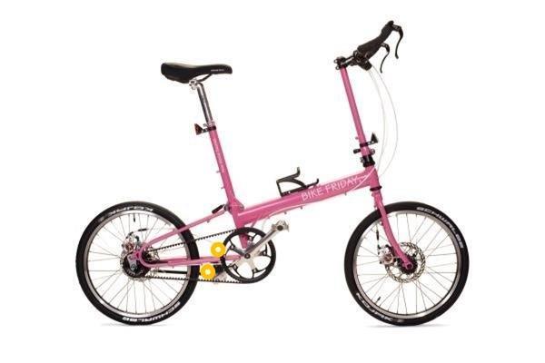
Not sure if I should start a new thread, but wanted to share my progress so far with one of Kepler's prototype brackets.

Please keep in mind I am a mechanical engineer, with very limited electrical experience! Anything electrical related that I have done may be wrong and should be questioned extensively. :D

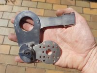
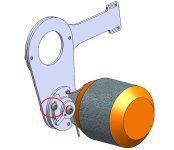
I installed the friction drive with a 230kv 50mm motor, driven by a VESC-X. My bike is mounted on a wind trainer which provides some wheel resistance at speed.

18v milwaukee battery running through a power meter and into the VESC. I set up the motor in FOC mode, which does seem quieter.

the system seems to run ok, outputs ~200 watts at full rpm, which increases when I apply the brake a bit.

230kv*18v= 4,140rpm. 50mm motor is 157mm cir. so at 18v I should be right around 39 km/h or 24mph, but am only at 29kmh or ~18mph.

This is my first time playing with any brushless motor, so I assume I am missing something. Does the Kv of a motor change as load is increased?

Hopefully I can throw more volts at the motor and get the speed I am looking for. Before I break anything, what settings in the VESC tool should I pay attention to before throwning 40v at it?

Next I need to figure out the throttle. Ideally I would mount a simple button to the bars that would provide a ~150W boost from 8-25mph. My plan is to limit battery current in the VESC software, and add a throttle that sends a 100% signal on the third sensor pin.

Any help from the more electrically capable members would be warmly received!

Here is the video of my setup
https://www.youtube.com/watch?v=_Rh217xJAMM


[youtube]Rh217xJAMM[/youtube]
 
the 40v battery works better, should be able to have assist up to 25mph now.

A couple IR images I took of the system after running ~10 mins in still air. No thermal issues at such a low power level.

FLIR0342.jpg

FLIR0346.jpg

View attachment 1

FLIR0352.jpg
 
Great stuff mhaskell. I am happy for you to post in this thread so we can keep all the information together.

You mechanical setup is spot on and should work well on the road.

In regards to speed I think RC style motors only give their kv rated rpm when free spinning. As soon as you load the motor, the best you get is around 70% of their rated kV. I have tested with a 50mm 230kV motor on 7S 18650 (26V nominal) and I max out at 43kph.

I need to do a bunch more testing on my vesc, but I have made a simple on/off analogue button using a modified servo tester. I will post up some more detail on this in the next few days.
 
I know its taking a while to release this drive but thorough testing is so important.

On the latest design I had deleted the third locking bolt on the end stop plates. This worked fine on the lighter 50mm motors but running the heavier 63mm motors I am finding the end stop plates are moving when riding on rough roads.

So this means I need to re instate the third locking bolt and modify the end plates to suit. Unfortunately I now need to get new locking plates cut and tested with the 63mm motor. Puts be back another week. My appologies to all those patiently waiting for the drive to become available.
 

Attachments

  • Drive.JPG
    Drive.JPG
    45.8 KB · Views: 3,626
I've run into a snag getting the throttle to work.

I am using a simple servo tester to provide input to the VESC. I want to combine the servo tester and a handlebar switch to provide either 0 or 100% throttle signal.

https://www.amazon.com/gp/product/B00SYEEMVW/ref=oh_aui_detailpage_o00_s00?ie=UTF8&psc=1

https://www.amazon.com/gp/product/B0195V8G4Q/ref=oh_aui_detailpage_o00_s02?ie=UTF8&psc=1

I unsoldered the potentimeter and measured its resistance as 2ohm at full throttle and 8.7kohm at no throttle

My thinking was to cut the center leg of the potentimeter and wire the switch in series, when the switch is off the resistance is infinite,and when it is on the resistance is ~2ohm. Is this anywhere close to correct to provide the needed 1us and 2us output signal from the tester to the VESC?

MOD-SRV-TEST-01B.jpg
MOD-SRV-TEST-01C.jpg
 
The Vesc can be controlled by either PPM or a 0-5V signal. Easiest way would be to use a potentiometer set up as a voltage divider to feed the ADC input on the Vesc. No need for servo testers, 3 wires and a poti is enough.
With the bldc tool you can activate and configure your prefered way of controlling the motor, e.g. motor current/duty cycle via PPM, ADC, UART etc.
 
Thanks for that payder. (Edit) So do you connect the output of the voltage divider to the ADC_EXT pin? Or alternately a 10K pot over the 3.3V and GND with the wiper to the ADC_EXT pin? Starting to get my head around this controller i think.
 
Back
Top