KONA Entourage Build Thread - middrive (pic heavy)

a half link chain can be shortened to fit easier since it's 2 half-link connections to make a normal link, and every link connects to the next, not outer/inner.

I run a 1/2" x 1/8" and it fits all my sprockets and cogs fine.
 
r3volved said:
a half link chain can be shortened to fit easier since it's 2 half-link connections to make a normal link, and every link connects to the next, not outer/inner.

I run a 1/2" x 1/8" and it fits all my sprockets and cogs fine.
ah ok. you can learn something new every day. thanks :)
 
Half link chains are available in both 1/8" and 3/32" widths, they can be sized closer to ideal than a full link chain but you would need to be very lucky for one to fit perfect and not require a tensioner. They do have another benefit, the shape of the side plates allows a little flex so when used as a drive chain they can be tensioned a little tight to prevent chain slap but under load they stretch a little so have that little slack on the return side like a correctly tensioned chain.

Another benefit is even wear, a conventional chain has 2 rollers attached together between the inner plates, there centre distance cannot change, so all of the stretch and wear occurs in the external link pivots resulting in a chain with uneven pitches, a half link wears equally which should be kinder to sprockets.

 
I kept the little idler on my chain-side of the GNG (belt version) using a half-link 1/2" x 1/8". It's helped to prevent any slack from wear, even though it doesn't look like it's doing much.
You can at least reduce the angle at the idler.
 
I like the future rendition better. Curves at the motor match better with the curvy flow of the initial frame. Controller looks to be better suited away from stray debris on the trail.
 
today was welding time again. as described some posts ago i wanted to remove the sharp edge and make it a bit rounder, and as well move the controller upwards.

2014-07-29 13.38.33.JPG
the old part was cut out

2014-07-29 13.47.36.JPG
fixed and ready to weld

2014-07-29 13.54.13.JPG
welding

2014-07-29 13.57.24.JPG
done welding, and sanding the welds down to a smooth surface. it looks a bit uneven, but this is because of the light reflection

2014-07-29 19.46.09.JPG
this is the chain tensioner and an idle roller so the chain won't scratch the bb

2014-07-29 19.46.17.JPG
and yes. i LOVE it. a broken taper :( 
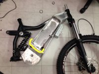
as i couldn't remove it, i smashed it hard with a hammer so it moved inside and i can close the hole with a weld and sand it down. then the controller will need a new location to be screwed down.

2014-07-29 19.46.29.JPG
 
and the story goes on. first thing to do was to close the whole from the taper. done. :)
next thing done were thicker spacers for the freewheel for a perfectly straight chainline:

IMG_0021.JPG
IMG_0022.JPG
then the frame was fixed in the mill to mill down the frame to the exact height of the installed motor. the heat sink will then be installed on the motor. the frame was made exactly even and then milled down.

IMG_0023.JPG
IMG_0025.JPG
i cut off the head of some screws and made them tapered. those where screwed into the frames holes, then the alloy plate was put onto it, some smahes with a rubber hammer and i had the exact location for the holes

IMG_0026.JPG
IMG_0030.JPG
 
i love it when everything fits. all screws went in without any play and where screwed down by hand

IMG_0033.JPG
then the alloy plate was sanded down to match the frame

IMG_0034.JPG
and now for the sad part: i used a 4mm miller for the fins, but even though i was very careful and cleaned it all the time, used cutting lubricant etc, it broke after the fifth fin. of course no spare millers where left and i have to wait for next week to finish it.
but it's looking REALLY nice already. just like i imagined it would look like :) 2 more hours of work and it should be done.

IMG_0036.JPG
 
i maybe got a problem. i want to move my controller up (for better looks and to safe it from mud) and to check if it got enough clearance from the front wheel i removed the fork's spring and compressed it all way down.

this is what it looks like:

IMG_0037.JPG
if i want to install the controller, the front wheel would definitely hit it. so the question is: how far will the fork compress with the spring installed? i tried to compress it, and fix it with some rope but i wasn't able to fully compress it.

IMG_0038.JPG
so any help is very welcome. will this work? or will i kiss the ground after the first big jump?
 
is it possible to put some spacers between fork and headset? I think of those washers to vary the height of the steerer on the fork..
 
madin88 said:
is it possible to put some spacers between fork and headset? I think of those washers to vary the height of the steerer on the fork..
no. not easily. i would need to remove the lower bearing cup from the fork and add spacers there. therefore i would need a longer steering tube as well. quite complicated and i would change the bike's geometry.
i could put the controller where i wanted to put it from the very beginning. but i would need to change the controller's case back from 12fet to 9fet so it will not be hit by the damper when it compresses. i'm not sure if it will get much air there and may become too hot?!
or i will put it back to the lower position in front where i had it lately - how good that i have all holes closed again and i need to drill new ones *ggg*

IMG_044.JPG
so the question is: silver controller or black one?
 
ok. to make it easier. here are all 3 positions in a seperate picture. which one should i choose?
first one is the most complicated one regarding cable guiding.
second one is the one i don't like from the way it looks
third one is the one where the controller's hit by the wheel

IMG_0045.JPG
View attachment 1
IMG_0047.JPG
 
yes it seems like the wireing will be more difficult if you mount it on top, but i guess heat will not be an issue because of the alu frame. If it has good contact with some kind of thermal paste in between it will be ok.
where would you let the wires go (beside the batteries?) and can you fit all your custom electronics in the smaller 9fet case?
 
is it possible to pass the wires here:
 

Attachments

  • IMG_0047.JPG
    IMG_0047.JPG
    51 KB · Views: 1,825
Position 1 looks nice and neat, plus you'll be the first to know when smokes pouring from it ! Lol . And paint it all black :D
 
no. wires would go that way:

IMG_0045.JPG
only problem: i can not hide the wire entry into the frame, so wires will be visible from the outside, and it will be quite a mess to guide the wires next to the parallel boards. it's quite crowded already.

i could do it the way you suggest, which would solve the space problem, but then there would be even more wire visible.
the other problem i have with mounting the controller there is that it's in the shifting and braking cable's way.
 
When you had the forks fully compressed had you removed the springs? if the springs were still in but coil bound would they allow the forks to compress that far, measure the spring wire dia and multiply by the number of coils to find the min compressed length. Or can you add a spacer inside the fork to limit travel, or between the fork crown and lower bearing.
It seems to close to allowing the controller to go at the front, surely you can find the little space required from somewhere?


Have you considered letting the controller into the front face and securing it to the next surface, it would still be exposed to air flow and also have protected invisible wiring and would give you the little extra space you need.
 
Tench said:
It seems to close to allowing the controller to go at the front, surely you can find the little space required from somewhere?

Have you considered letting the controller into the front face and securing it to the next surface, it would still be exposed to air flow and also have protected invisible wiring and would give you the little extra space you need.
thanks for your suggestions. unfortunately i don't understand what you are saying. :( where are you saying to install the controller? securing it to the next surface? can't follow that.
 
Tench said:
When you had the forks fully compressed had you removed the springs? if the springs were still in but coil bound would they allow the forks to compress that far, measure the spring wire dia and multiply by the number of coils to find the min compressed length. Or can you add a spacer inside the fork to limit travel, or between the fork crown and lower bearing.
It seems to close to allowing the controller to go at the front, surely you can find the little space required from somewhere?


Have you considered letting the controller into the front face and securing it to the next surface, it would still be exposed to air flow and also have protected invisible wiring and would give you the little extra space you need.

Because you took the springs out of the forks to test travel this allowed much more travel .. so with the springs fitted this will give you at least 6-10cm of less travel, Which I think would have made it fine.
 
gwhy! said:
Tench said:
When you had the forks fully compressed had you removed the springs? if the springs were still in but coil bound would they allow the forks to compress that far, measure the spring wire dia and multiply by the number of coils to find the min compressed length. Or can you add a spacer inside the fork to limit travel, or between the fork crown and lower bearing.

Because you took the springs out of the forks to test travel this allowed much more travel .. so with the springs fitted this will give you at least 6-10cm of less travel, Which I think would have made it fine.

that was the part that i DID understand indeed. ;) but i'm not sure that your assumptions are correct and i will have to do some more investigations. the fork has 170mm travel. if i measure full length (there is a little rubber band on one holm) and compare it to fully compressed (with coil removed) it's 170-175mm. so it seems the coil is not the limiting factor and adding spacers will reduce travel, but i'm not sure that the coil acts as travel stopper and is meant to do so (will the top cap be strong enough for that?).
on the other hand it would be stupid to buy a downhill/freeride bike with massive travel and then reduce it to fit that bl***y controller. ;(
damn i'm really p****d. all ready to be painted and now such a bad show stopper.
 
Back
Top