
You are using an out of date browser. It may not display this or other websites correctly.
You should upgrade or use an alternative browser.
You should upgrade or use an alternative browser.
KT motor controllers -- Flexible OpenSource firmware for BMSBattery S/Kunteng KT motor controllers (0.25kW up to 5kW)
- Thread starter casainho
- Start date
Romantas
1 mW
- Joined
- Aug 31, 2018
- Messages
- 18
stancecoke said:be aware, your photo shows only the breakout board, not the BT-Module itself.
The tutorial, how to connect the module can be found in chapter 6 There is the link to an ebay-offer for the HC-05 also.
regards
stancecoke
I already bought it today
")
honya96
1 kW
Hello guys, I see some very interesting stuff going on here, would like to try but I am using different controllers right now 
I am trying to convince (or bribe) my brother to write a code for arduino nano, to send speed, battery bars, watts and motor temp ( for now) to LCD3, so it can work with any controller.
I guess its well documented here somewhere how to do it, maybe we can also reuse some code..
can you please point me to something what can help us?
Thanks a lot.
casainho
10 GW
- Joined
- Feb 14, 2011
- Messages
- 6,058
WAIT!! Instead, ask your brother to program directly the LCD3!! We developed OpenSource firmware for LCD3, see here this user doing a review and see it using the LCD3 and you will see new menus on LCD3 that you never saw beforehonya96 said:I am trying to convince (or bribe) my brother to write a code for arduino nano, to send speed, battery bars, watts and motor temp ( for now) to LCD3, so it can work with any controller.
For you understand, we developed TSDZ2 mid drive motor controller firmware + LCD3 firmware, and we make both firmware communicating the LCD3 supports configuration of the many advanced features of our firmware for TSDZ2, like you configure on LCD3 your battery voltage, number of cells, etc that on KT firmware you can only do on config.h file or the config Java app:
[youtube]IrWn6e8bIuQ[/youtube]
honya96
1 kW
casainho said:WAIT!! Instead, ask your brother to program directly the LCD3!! We developed OpenSource firmware for LCD3, see here this user doing a review and see it using the LCD3 and you will see new menus on LCD3 that you never saw beforehonya96 said:I am trying to convince (or bribe) my brother to write a code for arduino nano, to send speed, battery bars, watts and motor temp ( for now) to LCD3, so it can work with any controller.
I wanted the arduino as kind of Cycle Analyst, so I connect things to it. Seems easier to me. Firstly speed only and then adding more.
With custom fw and as you say "program lcd3 directly" I will have to connect hall signal temp sensor etc directly to lcd3.
Possible way to do it is (maybe) also use output from controller, (sabvoton, kelly) which sends a lot of data and "teach" lcd3 to show them. But this way theres no chance to implement PAS level (modulating throttle signal by arduino or STM32 board or directory by lcd3's STM8.)
casainho
10 GW
- Joined
- Feb 14, 2011
- Messages
- 6,058
Ok I understand and yes, that seems the best idea!! Good luck!!honya96 said:I wanted the arduino as kind of Cycle Analyst, so I connect things to it. Seems easier to me.
I am thinking about building a stealth ebike with a 201rpm Q100H rear hub and KT open source firmware on an S06S.
The idea is not to use much assist on the flat, or go fast. The idea is to have a light ebike that feels like a regular bike but gives real assist on hills. The Q100H is 2.1kg and low rpm. I have a heavier DIY ebike that I like, so I'm not new to ebikes, but I am new to open source.
Looking for advice and opinions:
I'd like to simulate the setup, to use the simulator at ebikes.ca I need:
If anyone can help with those values or a no-load chart I can check if I am being realistic about hill climbing ability. (My target is 7mph on 8% grade with 100W human input).
The idea is not to use much assist on the flat, or go fast. The idea is to have a light ebike that feels like a regular bike but gives real assist on hills. The Q100H is 2.1kg and low rpm. I have a heavier DIY ebike that I like, so I'm not new to ebikes, but I am new to open source.
Looking for advice and opinions:
- The biggest advantage for me would be higher efficiency at lower speed due to FOC. How significant is this really?
- Is https://opensourceebikefirmware.bitbucket.io/windows_instructions/index.html the best instructions?
- Is there an easiest-to-use display? LCD-3?
- My other ebike has a 52V battery. Should I even consider using it or is it best to stick to 36V? The BMS battery S06S is 36V, I would have to find a 48V KT controller equivalent to S06S, the Q100H is nominally 36V, etc.
I'd like to simulate the setup, to use the simulator at ebikes.ca I need:
- a0: Hysteresis torque of the motor in Nm. You can derive it from the no-load current at low speeds
- a1: Eddy current torque of the motor, (N-m/(Rad/sec)). You can derive it from the slope of the no-load current vs. rpm
- Battery amperage for the S06S (the nominal 15A?)
- Phase amperage for the S06S?
If anyone can help with those values or a no-load chart I can check if I am being realistic about hill climbing ability. (My target is 7mph on 8% grade with 100W human input).
stancecoke
1 MW
honya96 said:I guess its well documented here somewhere how to do it, maybe we can also reuse some code..
can you please point me to something what can help us?
Thanks a lot.
I think the Forumscontroller is exactly what you are looking for!
https://github.com/jenkie/Arduino-Pedelec-Controller
Sadly the documentation is mainly in german
regards
stancecoke
honya96
1 kW
cpn said:I had phase to phase short on 18fet open source firmware controller. It looks like as a result transistor is burned. Can somebody point me on right part I am not sure if is Y1 or Y2
Will check that when I get home. :wink:
honya96
1 kW
honya96 said:cpn said:I had phase to phase short on 18fet open source firmware controller. It looks like as a result transistor is burned. Can somebody point me on right part I am not sure if is Y1 or Y2
Will check that when I get home. :wink:
It is Y2
Valopallo
100 W
- Joined
- May 29, 2018
- Messages
- 125
honya96 said:Valopallo said:Please explain, what would be the problem with the battery? I understand that 10ah isn't much range if drawing 40Amps from it but is there something else like heat problems involved when going this high current draw?
Also, what do you mean by; "But I am still not running it reliably on Direct motor" ?
Well, I know nothing about programing So I cant get it to run reliably, its still better Stock.
But Stancecoke Is running Direct motor with it..
You Have some Brand battery in plastic case with bms inside? Send photos maybe...
Overheating of the cells should not be that bad, but if it has 15A bms with 30A overcurrent protection, it Will shut off.
Ok. Finally got the time to open the battery case. Do these pictures give any information about my BMS or it's overcurrent protection?
https://imgur.com/a/30EvYLc
EDIT: Found it. http://www.spardbattery.com/PW-10SM-30092-2-20
I'm in the process of modifying my S06S for higher voltages. Can anyone tell me the purpose of C1/C5/C14? (https://github.com/KingQueenWong/bmsbattery_s06s_controller_hardware/blob/master/S06S-Controller.PDF upper right corner) I wonder if their voltage rating needs to be raised if the max input voltage is, say, doubled.
honya96
1 kW
Valopallo said:Ok. Finally got the time to open the battery case. Do these pictures give any information about my BMS or it's overcurrent protection?
https://imgur.com/a/30EvYLc
EDIT: Found it. http://www.spardbattery.com/PW-10SM-30092-2-20
If you need more power, you can connect discharge without bms, just a fuse. And still have safe charging through bms. :wink:
honya96
1 kW
1N4001 said:I'm in the process of modifying my S06S for higher voltages. Can anyone tell me the purpose of C1/C5/C14? (https://github.com/KingQueenWong/bmsbattery_s06s_controller_hardware/blob/master/S06S-Controller.PDF upper right corner) I wonder if their voltage rating needs to be raised if the max input voltage is, say, doubled.
I guess they dont, Vbst should be from some regulator so it remains the same.. But i dont recommend trying this. Buy 72v 12fet and cut case to ~50mm
honya96
1 kW
stancecoke said:honya96 said:I guess its well documented here somewhere how to do it, maybe we can also reuse some code..
can you please point me to something what can help us?
Thanks a lot.
I think the Forumscontroller is exactly what you are looking for!
https://github.com/jenkie/Arduino-Pedelec-Controller
Sadly the documentation is mainly in german
regards
stancecoke
We had a conversation about this allready.. I guess I did not find it easy and good enough, but thanks anyway :wink:
Yes, the FETs are controlled with around 15V from the LM317, however one leg of C1/C5/C14 (the negative one in fact) sits directly on the motor phase, so it must be involved in the load circuitry somehow.honya96 said:1N4001 said:I'm in the process of modifying my S06S for higher voltages. Can anyone tell me the purpose of C1/C5/C14? (https://github.com/KingQueenWong/bmsbattery_s06s_controller_hardware/blob/master/S06S-Controller.PDF upper right corner) I wonder if their voltage rating needs to be raised if the max input voltage is, say, doubled.
I guess they dont, Vbst should be from some regulator so it remains the same..
Surely you jest? The 12FET PCB extends the entire length of the case: https://opensourceebikefirmware.bitbucket.io/development/images/15-1.pngBut i dont recommend trying this. Buy 72v 12fet and cut case to ~50mm
honya96
1 kW
1N4001 said:Yes, the FETEs are controlled with around 15V from the LM317, however one leg of C1/C5/C14 (the negative one in fact) sits directly on the motor phase, so it must be involved in the load circuitry somehow.honya96 said:1N4001 said:I'm in the process of modifying my S06S for higher voltages. Can anyone tell me the purpose of C1/C5/C14? (https://github.com/KingQueenWong/bmsbattery_s06s_controller_hardware/blob/master/S06S-Controller.PDF upper right corner) I wonder if their voltage rating needs to be raised if the max input voltage is, say, doubled.
I guess they dont, Vbst should be from some regulator so it remains the same..
Surely you jest? The 12FET PCB extends the entire length of the case: https://opensourceebikefirmware.bitbucket.io/development/images/15-1.pngBut i dont recommend trying this. Buy 72v 12fet and cut case to ~50mm
Lenght, but not width, that can be cut.
Xnyle said:It would be easy to create another non technical dashboard screen.
But then its main purpose is to know and change what's going on inside that black or silver box.
For me it will replace the original display, there are cheap smartphones for under 50€/$ out there so i will just mount one of them and have more flexibility and insight than any commercially available display could ever provide.
For almost the same price that is.
Just have to find one that looks really crappy, so it doesn't get stolen :wink:
Hi Xnyle,
In the beginning, while I was thinking of using this open-source firmware I was attracted by the idea of controlling the ebike from a mobile phone. I made the replica Lishui BT adapter and tested it on the controller which showed some limited information on the mobile phone display. I strongly believe this new BT app is a great starting point to a complete BT display solution for this project and thanks very much for all your efforts.
As a beta tester, I tested BluOsec app with the Torque-Simulation mode.
I understand that this version of the app is technical and intended for the developers, debuggers.
I would like to know more about some values and terms like: Correction value, Setpoint, PAS values
Offroad Enabled
App works just fine and shows all the values except the SPEED! No speed value!
I got a correction value of -20, -24 is that normal?
I think changing values on the run has not been implemented yet. I’ve tried to change some values but found out that only max speed value can be changed.
I’m in favor of a normal use dashboard display (on mobile phone), perhaps if possible, showing a combination of technical and non-technical information. As you have mentioned a cheap smartphone will really be an attractive replacement for any other display.
Cencen
Xnyle
10 W
- Joined
- Sep 3, 2018
- Messages
- 76
Not sure if you're using the latest versions.
You can change everything that's grey in the Java tool and as far as i know everything works.
If something is not working, please make a screenshot and tell us what you did, what you expected, what you got instead, what you think might be the reason you got something different.
For instance "Speed" refers to two different values on the Fragments, Erps speed and external sensor speed. If you don't have a sensor the latter one will always be zero.
Also please make sure you always use the latest version/commit and always use the apk of that very commit. Stuff is still changing in communication protocol, so old versions might not work.
If you'd like a quick response better post in the German forum, no one will blame you for posting English there
Xnyle
10 W
- Joined
- Sep 3, 2018
- Messages
- 76
I would like to know more about some values and terms like: Correction value, Setpoint, PAS values
Offroad Enabled
Yes documentation is key, but my motivation to write a good documentation on top is... well
Correction value is an adjustment to the motor specific angle (the angle between what the hallsensors say and where the motor really is).
It should be zero. You should adjust the angle until it is. Value is normally between 200 and 250.
Setpoint is duty cycle, ask stancecoke why it is/was called this way
Offroad enabled is illegal in Germany
If enabled, we will all go to jail, so don't ask about it.PAS values, which ones?
stancecoke
1 MW
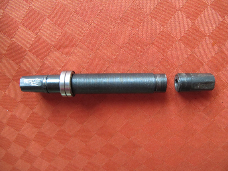
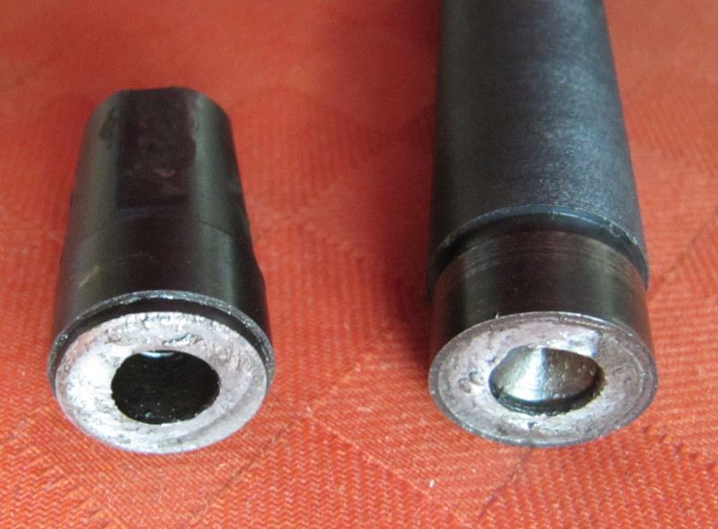
Today, I broke the shaft of my BMS-Battery bottom bracket torquesensor, too. Sadly I can't find casainho's pictures with his broken part, to compare if they broke in the same area...
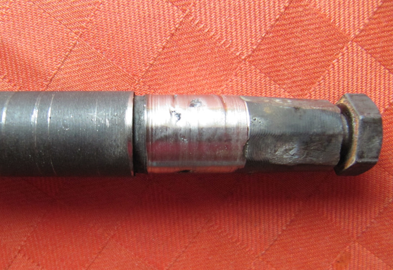
I've welded the shaft and I hope this will work until I receive my new Sempu 3rd gen.
regards
stancecoke
I've welded the shaft and I hope this will work until I receive my new Sempu 3rd gen.
regards
stancecoke
geofft
10 kW
I've welded the shaft and I hope this will work until I receive my new Sempu 3rd gen.
Glad to see I'm not the only one with a mig welder amongst his toys..
Decent looking weld but it will get a stern test in that location...
geofft
10 kW
Just thought I'd show you my latest attempt at taming the simmering series resistor and LM317:-
Bought a couple of these:-
https://www.ebay.co.uk/itm/Through-...e=STRK:MEBIDX:IT&_trksid=p2057872.m2749.l2649
...unfortunately, as you can see, they're not cheap. Splayed the legs out to fit the resistor pcb holes:-

....also rotated the LM317 so it could be clamped against the case for improved heatsinking. Initially intended to 'cross its legs' but then realised that re-wiring the outer pcb tracks was an easy and neater solution. Had to add an insulator as the LM317 tab is not isolated.
The end result looks pretty neat:-
...all seems to run nice and cool so far but haven't given it a long test yet.
Bought a couple of these:-
https://www.ebay.co.uk/itm/Through-...e=STRK:MEBIDX:IT&_trksid=p2057872.m2749.l2649
...unfortunately, as you can see, they're not cheap. Splayed the legs out to fit the resistor pcb holes:-
....also rotated the LM317 so it could be clamped against the case for improved heatsinking. Initially intended to 'cross its legs' but then realised that re-wiring the outer pcb tracks was an easy and neater solution. Had to add an insulator as the LM317 tab is not isolated.
The end result looks pretty neat:-
...all seems to run nice and cool so far but haven't given it a long test yet.
stancecoke
1 MW
Nice work! Xnyle and me, we both have replaced the resistor and the LM317 by a DC/DC converter and both have trouble with them... I burned 4! converters while experimenting with switching off the PWM while no power is wanted and switching it on again when power is needed while the bike is moving... I buyed a pack of ten, so I was able to fix the controller fast
The new function (now stable :wink: ) can be found in a new branch. It needs a motor specific constant defined in the config.h
Of course this function is only interesting for direct drive motors.
regards
stancecoke
The new function (now stable :wink: ) can be found in a new branch. It needs a motor specific constant defined in the config.h
Of course this function is only interesting for direct drive motors.
regards
stancecoke
Similar threads
- Replies
- 129
- Views
- 46,822
- Replies
- 2
- Views
- 3,608