The firmware on it's current state, is a serial killer of Kuntengs
")
- On the last 3 days, I wanted to make S12S working on my Q100 motor and 48V battery. Before, I only tested the firmware on S06S controller, Q85 motor and 24V battery.
- On the last 3 days did repair my S12S 3 times, exchanging burned mosfets. In the end, I started to use S06S with 48V and I also burned all my S06S!!
- Seems that my Q100 motor is not working correctly (with original controller KU123, sensorless 6 steps, was failing already sometimes) and after buying a S12P to my friend of local workshop for EBikes, it almost always gives the error on LCD about bad hall sensors although even if the wheel run but makes some noise. The S06P of my son EBike also can't run it, can start the motor but after makes noises and fails.
- The controllers with original firmware that I tested with my Q100, they could not run the motor but they never burned. Before I could understand that Q100 is not working correctly, I burned all my controller with our OpenSource firmware!! Why? I now think that was because I had cruise control enable and with that is easy to let the controller giving constant energy to the motor (I did just that) and even if the current controller works, the controller can't handle it many seconds constant. I verified that the controllers with original firmware will shutdown itself after a few seconds if the motor don't rotate -- next task to implement on the firmware!! and I think maybe on the fast loop/low level.
For what I could test, the S12S were working correctly. I had to exchange to were FOC was done, I could see it failing before and working as expected after.
I will need to take a break to make other things and at the same time I am now waiting for new controllers from BMSBattery. Maybe I will be able to repair my S12S...
stancecoke said:
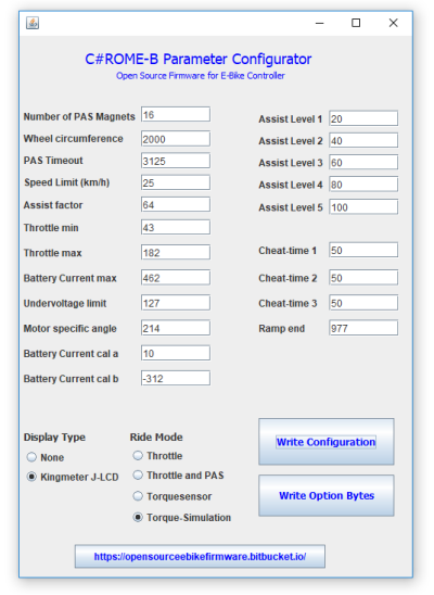
How can we merge our branches, now? I think, mainly we have to have all user relevant parameters in the config.h to make the Java-tool work and then have to implement the ride modes throttle+pas, torque-simulation and torquesensor to the master.
As you can see, I am being very busy to test the firmware and trying to take it out from the test/development bench. And it is not ready yet for no developers.
This is not going as fast as I expected, but because of complexity of the project. We are getting a lot of help!! but the project is a bit more complex than I thought before starting it
Since it seems very easy to burn controllers (and maybe also unprotected batteries packs), why not focus first on a small set of hardware options and for developers/advanced users only??
Maybe I would for now focus of a config header file only and BMSBattery S motor controllers (sinewave only!) + LCD, motors and throttle, PAS and torque sensor. For instance, my friend have some controllers from Kunteng, bought from them directly and they have different hardware configurations, like one you had, without phase B current sensor.
What is than the advantage of this firmware over the original? The original works very well. With our firmware we can get more flexibility but I think we are not there yet, at least it is the reality for me after all this weeks working almost full time on this project and trying on real ebikes.