KT motor controllers -- Flexible OpenSource firmware for BMSBattery S/Kunteng KT motor controllers (0.25kW up to 5kW)

Geege33708 said:
Does anyone know how I would hook up one of these controllers up to my Magic Pie 2. I have all the bells and whistles on the Golde Motor, but I don't need cruise control. The reverse is pretty cool though, I am looking for advice, Thanks, Geege
Firmware is a bit far from be finished but when we have a stable version, we will have information on how to connect a motor and make some tests to make it working with this controller, if possible.
 
casainho said:
They say the connector/cable is different to the regular S06S and I will need to make the connector -- no issue for me and I will even document for other users....
Do you know of potential disadvantages of BMSBattery torque sensor?? -- because I think I will go with it because of lower price and availability from BMSBattery, at unit and that works with S06S controller.

I documented this sensor in detail in the german forum(of course in german, i think google translate will help ;))
The pinout and the connection to the S06ST is shown here.

I think this sensor is OK, but I had some trouble that the mechanic parts locked from time to time, until I mounted a stronger spring to bring the mechanic parts back to their home position safely.

Regards
stancecoke
 
stancecoke said:
casainho said:
They say the connector/cable is different to the regular S06S and I will need to make the connector -- no issue for me and I will even document for other users....
Do you know of potential disadvantages of BMSBattery torque sensor?? -- because I think I will go with it because of lower price and availability from BMSBattery, at unit and that works with S06S controller.

I documented this sensor in detail in the german forum(of course in german, i think google translate will help ;))
The pinout and the connection to the S06ST is shown here.

I think this sensor is OK, but I had some trouble that the mechanic parts locked from time to time, until I mounted a stronger spring to bring the mechanic parts back to their home position safely.
GREAT!! I wanted internal pictures of the sensor and signals details and you just did it!! :)

I have some questions:
1. using the sensor, does it changes the way you need to pedal? what are the changes compared to using the original bicycle bottom bracket?
2. does the analog signal indicate the level of force or it always saturate and seems to be the case on the first 5 cycles on the picture:
index.php

3. are you still using this sensor on your bicycle?
 
casainho said:
1. using the sensor, does it changes the way you need to pedal? what are the changes compared to using the original bicycle bottom bracket?

There is no change in the way to pedal. The sensor comes with a normal square tapered spindle. It's just a little wider on the left side, the q-factor is a little bigger compared to a "normal" bottom bracket.


casainho said:
2. does the analog signal indicate the level of force or it always saturate and seems to be the case on the first 5 cycles on the picture:
The saturation force depends on the chainwheel diameter. (~150N at small chainwheel, ~250N at big chainwheel). Below this the voltage is proportinal to the force.

casainho said:
3. are you still using this sensor on your bicycle?
actually the sensor is lying around on my desk, as I got the Sempu sensor now.

casainho said:
What timmings do you refer?

Code:
112 ui16_temp_delay = TIM2_GetCounter (); 
113 //	if ((ui16_temp_delay - ui16_throttle_counter) > 25) 
114 	if ((ui16_temp_delay - ui16_throttle_counter) > 100) 
115         { ...

please can you explain this part.

Regards
stancecoke
 
casainho said:
What timmings do you refer?

Code:
112 ui16_temp_delay = TIM2_GetCounter (); 
113 //	if ((ui16_temp_delay - ui16_throttle_counter) > 25) 
114 	if ((ui16_temp_delay - ui16_throttle_counter) > 100) 
115         { ...

please can you explain this part.
Timer2 is configured to increment at each ~1ms.
That piece of code is on the main loop and should have the code that don't need exact timings. The loop starts by looking if from last time of executing throttle code, has passed 25ms and if so, executes the code and starts again the counting.
My idea is to use a break; after the end of that code, so the loop restarts before jumping to next code that will be similar, another counter for run another feature code (like UART sending/received and processing code for the LCD that is not done yet).
The idea is to make most priority feature code at first in loop row (breaking at the end of each feature) and having different times for each feature, the higher times values will be the less priority and on the bottom of the row.
I think Real Time Operations Systems (RTOS) for microcontrollers, implement priorities of tasks kind of like these way.
So, the only interrupt is the most priority and realtime task: motor control fast loop / PWM cycle interrupt, happening at every 64us. Let's say that this fast loop uses 60us, so only 4us (6,25%) will be left free to do the processing on the main loop feature codes.

I would like to have the code optimized on the PWM cycle interrupt to decrease the period to 50us and so having a PWM frequency of 20kHz instead of the 16kHz of original firmware -- main objective would be to have this controller be able to run faster motors.
I believe Q75 motor is one of that fast motors, probably even faster than Q85. On contrary, a direct drive motor like the ones used on electric unicycles, have lower eRPM values so S06S can control them ok.
 
I will make a talk about this project, with title "Develop embedded soft/firmware for chinese motor controllers" in PixelsCamp, Lisbon, on 30 September.

PixelsCamp is the most yearly relevant event, in Portugal, for the software, firmware and hardware developers -- 3 days of non-stop tech, talks, workshops and a 48 hour programming competition: https://pixels.camp/


The description of my talk - original link: https://github.com/PixelsCamp/talks/pull/161

Develop embedded soft/firmware for chinese motor controllers

Description

Since some years, I am being developing OpenSource firmware for the chinese electric motor controllers that are used on small electric vehicules: hoverboards, skates, unicycles and bicycles.

This chinese controllers are dirty cheap, capable and with ok quality. Since they optimize their products for price, they have very limited resources - developing firmware for their controllers means learning how to make "the thing" in a unique and creative ways, optimizing all the processing power and memory used.

Why I decided strategically to develop firmware for the cheap chinese controllers? Because the market is flooded with them: they work well and are easy to get. This OpenSource firmware is the first in the world and I hope it will be used by many users as possible, shapping the future like Arduino did.

I would like to present my experience, from developing the firmware and up to try gather a community and contact with people all over the world (using a lot Google translator for german, chinese, etc).
 
OK, I think I have to learn how the I/O Pins of the Mosfets are set/reset, to unterstand why the timing with interrupts is that critical....

Good Luck with your talk!

Regard
stancecoke
 
stancecoke said:
OK, I think I have to learn how the I/O Pins of the Mosfets are set/reset, to unterstand why the timing with interrupts is that critical....
The timings are critical to put the voltage on the motor phase wires:
- with the correct wave shape ("Sinewave" or Space Vector Modulation (SVM))
- with correct synchronization with hall sensors signals (here the important the is phase B current wave form synchronized with hall sensors, for doing FOC. But phase B current timing = f( voltage motor phase B timming) ).

The wave form values are stored on the ui8_svm_table [SVM_TABLE_LEN] wich is a 256 bytes array (sinewave or SVM wave defined on BLDC_SPWM_Lookup_tables.ods file). This values need to be put as duty_cycle of PWM. And they need to be scaled based on the throttle value (as on current firmware, not considering things like future speed or torque control to be developed), like if throttle value will be from 1% to 100% and will multiply to each ui8_svm_table[] value.
Then are the timings, that need to be calculated in a way that duty_cyle is updated on correct time, and no more than every 64us.

Every 64us PWM cycle, next new value of duty_cycle of PWM must be calculated to apply on the next cycle. If this calculation don't happens between each cycle and at some random time, the synchronization of phase B current with hall sensors signals will be lost and motor will work without the most efficiency possible (loss of energy, controller getting hotter) and motor making noise.

What you need to learn about the timings are the PWM schemes and about FOC:
- https://opensourceebikefirmware.bitbucket.io/Motor_control--PWM_schemes--So,_Which_PWM_Technique_is_Best_(Part_1).html
- https://endless-sphere.com/forums/viewtopic.php?f=30&t=87870&p=1297642&hilit=shane+colton#p1297642
- https://eggelectricunicycle.bitbucket.io/FOC--Shane_Colton_documentation_and_firmware.html

But try to just have an overview and let that part of PWM and FOC with me. If you prefer you can focus on the PAS and torque sensors.

After having the motor working with simplified FOC, next things that need to be done:
- phase B max current control (I did this before on the EGG electric unicycle)
- over current protection (I did this before on the EGG electric unicycle)
- speed control loop AND phase B max current control; for throttle control: https://opensourceebikefirmware.bitbucket.io/Motor_control--Throttle_Control_Modes.html (new to me)
- UART / LCD (I did this before)
- bluetooh hardware module (I did this before on the EGG electric unicycle)
- Android app for bluetooth control (I did this before on the EGG electric unicycle)
- regen (kind of new to me)
- generic motor controller for Arduino, accepting control commands by UART
- etc etc :)
 
OK, so I need another time base, as the call of the adc_read_throttle each 100ms is to slow. The PAS-pulse cycle duration at a cadence of 120 rpm is about 15 ms (32 pulses/revolution). I think i need a resolution of 1ms at least.
Do you think that's OK, or will it cause trouble for the PWM?

Is there need for software-debouncing or are the digital signals hardware-debounced properly?

Should I place the PAS and SPEED handling into the GPIO include?

regards
stancecoke
 
stancecoke said:
OK, so I need another time base, as the call of the adc_read_throttle each 100ms is to slow. The PAS-pulse cycle duration at a cadence of 120 rpm is about 15 ms (32 pulses/revolution). I think i need a resolution of 1ms at least.
Do you think that's OK, or will it cause trouble for the PWM?
1ms is a lot fast... but wait, PAS digital signal is connected to PD0 TIM3_CH2 and TIM3 and TIM3 has 3 independent channels for Input Capture like channel 2 -- this means you should be able to configure TIM3_CH2 to count the time between each pulse!! Seems the best way to do it, to avoid burning processing time.

See this example: STM8S_StdPeriph_Lib/Project/STM8S_StdPeriph_Examples/TIM1/TIM1_Input_Capture

stancecoke said:
Is there need for software-debouncing or are the digital signals hardware-debounced properly?
Seems input capture have that option but I never needed debounce, like for instance hall sensors signals that have high noise. Compare on the schematic but I guess this both inputs will have the capacitor + resistor to make the low pass filter.

The torque analog signal is to be connected to throttle input?

stancecoke said:
Should I place the PAS and SPEED handling into the GPIO include?
Everything about PAS, I would create a pas.c/.h file and put there the code.

Please create your branch starting from SVM branch. Like create a branch with name "pas" and work there -- you can do whatever you want there. In the end (or at any stable version), we can merge your branch/code to the SVM one.
 
I buy a LSW659-94-1F Controller which cost $27(180RMB).Now i received it. :D
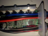
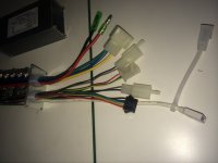
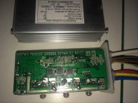
The board's information:
LM324(1 unit)
0.002OHm SHUNT(3 unit)
STM32FEBKC6T6(1 unit)
IRS2003(3 unit)
78M05(1 unit)
AMS1117(1 unit)
STP110N7F6(6 unit)
 

Attachments

  • 20170817150294418859951bbc8a2be.jpg
    20170817150294418859951bbc8a2be.jpg
    288.1 KB · Views: 2,758
  • 20170817150294423359951be9de191.jpg
    20170817150294423359951be9de191.jpg
    173.1 KB · Views: 2,758
  • 20170817150294479559951e1baac17.jpg
    20170817150294479559951e1baac17.jpg
    361.7 KB · Views: 2,758
KingQueenWong said:
I buy a LSW659-94-1F Controller which cost $27(180RMB).Now i received it. :D
The board's information:
LM324(1 unit)
0.002OHm SHUNT(3 unit)
STM32FEBKC6T6(1 unit)
IRS2003(3 unit)
78M05(1 unit)
AMS1117(1 unit)
STP110N7F6(6 unit)
Thank you!! That's great!!

With that components list and the pictures, I think you don't need to make the schematic. The build quality seems very good.
I have questions:
1. that controller, seems to not have LCD connection, right?
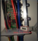
2. can you please identify which pins on the microcontroller are connected the pins for the programming header?
3. searching on google, I can't find anything about LSW659-94-1F and nor even Lishui site controller box selection shows that controller. Were did you bought it?
 
1. that controller, seems to not have LCD connection, right? (You are right)
2. can you please identify which pins on the microcontroller are connected the pins for the programming header? (You can see the below picture.)
3. searching on google, I can't find anything about LSW659-94-1F and nor even Lishui site controller box selection shows that controller. Were did you bought it? (https://item.taobao.com/item.htm?spm=a1z1r.7974869.0.0.36434a1uTgs2c&id=36491121354,I contact with the Lishui's sales to buy.)
 

Attachments

  • 111.jpg
    111.jpg
    63.8 KB · Views: 2,743
I just created an account at github and forked your project (I don't know if that's the right way to proceed...)

I'll try to add PAS, SPEED and Torque (=Throttle) function in the way I did in my pre-controller project and test it with a Shengy Central Motor. (I think that's the fastest running motor that I own, as I prefer direct drives :D )

regards
stancecoke
 
KingQueenWong said:
1. that controller, seems to not have LCD connection, right? (You are right)
2. can you please identify which pins on the microcontroller are connected the pins for the programming header? (You can see the below picture.)
3. searching on google, I can't find anything about LSW659-94-1F and nor even Lishui site controller box selection shows that controller. Were did you bought it? (https://item.taobao.com/item.htm?spm=a1z1r.7974869.0.0.36434a1uTgs2c&id=36491121354,I contact with the Lishui's sales to buy.)
1. I would then prefer the LSW-675 on selling from BMSBattery, because it includes the same programming port and another connector for the LCD / UART.
2. So their app is programming the firmware directly. Their app seems to encrypt the firmware file but anyone could do middle man attack and look at the firmware that is flashed by looking at that pins during programming.
But having this connector outside is great for development as any user will be able to flash the firmware without need to touch/open the controller.
 
stancecoke said:
I just created an account at github and forked your project (I don't know if that's the right way to proceed...)
I think that way will give more work later, because you will need to do pull requests later. I think is faster for you to have direct write access -- you just need to send me you github user ID.

stancecoke said:
I'll try to add PAS, SPEED and Torque (=Throttle) function in the way I did in my pre-controller project and test it with a Shengy Central Motor. (I think that's the fastest running motor that I own, as I prefer direct drives :D )
Ok.

And after testing the "sine wave" as original firmware, the motor runs ok but still have the same issue at high speeds -- I can't find an angle that work well. I don't know if this is a limitation of the controller or the motor... I will keep doing more tests and maybe I will try my electric unicycle motor that is a direct drive one.
 
casainho said:
stancecoke said:
I just created an account at github and forked your project (I don't know if that's the right way to proceed...)
I think that way will give more work later, because you will need to do pull requests later. I think is faster for you to have direct write access -- you just need to send me you github user ID.
[/quote]
Ok, just found you on github because you forked the repo. I added you as a member of https://github.com/OpenSource-EBike-firmware and you need to accept the invitation so you will get write access -- you just need to git clone the repo now.
 
Do you expect trouble with interrupt handling on port D for the PAS signal, as the UART pins are on Port D, too?
How can you read out which source triggered the interrupt on the port. I guess you can read it from a certain register?!

Regards
stancecoke
 
stancecoke said:
Do you expect trouble with interrupt handling on port D for the PAS signal, as the UART pins are on Port D, too?
How can you read out which source triggered the interrupt on the port. I guess you can read it from a certain register?!

On Linux Ubuntu, install using apt-get the "gitg" software.
Then, on sources folder, on terminal, execute gitg and you will have a grafical view of the git repo, including navigation of files at any commit. Go back to when I did the first code using the hall sensors interrupt and see how I configured only each specific pin to have interrupt.
 
casainho said:
stancecoke said:
Do you expect trouble with interrupt handling on port D for the PAS signal, as the UART pins are on Port D, too?
How can you read out which source triggered the interrupt on the port. I guess you can read it from a certain register?!
On Linux Ubuntu, install using apt-get the "gitg" software.
Then, on sources folder, on terminal, execute gitg and you will have a grafical view of the git repo, including navigation of files at any commit. Go back to when I did the first code using the hall sensors interrupt and see how I configured only each specific pin to have interrupt.
See here:


typedef enum
{
GPIO_MODE_IN_FL_NO_IT = (uint8_t)0x00, /*!< Input floating, no external interrupt */
GPIO_MODE_IN_PU_NO_IT = (uint8_t)0x40, /*!< Input pull-up, no external interrupt */
GPIO_MODE_IN_FL_IT = (uint8_t)0x20, /*!< Input floating, external interrupt */
GPIO_MODE_IN_PU_IT = (uint8_t)0x60, /*!< Input pull-up, external interrupt */
GPIO_MODE_OUT_OD_LOW_FAST = (uint8_t)0xA0, /*!< Output open-drain, low level, 10MHz */
GPIO_MODE_OUT_PP_LOW_FAST = (uint8_t)0xE0, /*!< Output push-pull, low level, 10MHz */
GPIO_MODE_OUT_OD_LOW_SLOW = (uint8_t)0x80, /*!< Output open-drain, low level, 2MHz */
GPIO_MODE_OUT_PP_LOW_SLOW = (uint8_t)0xC0, /*!< Output push-pull, low level, 2MHz */
GPIO_MODE_OUT_OD_HIZ_FAST = (uint8_t)0xB0, /*!< Output open-drain, high-impedance level,10MHz */
GPIO_MODE_OUT_PP_HIGH_FAST = (uint8_t)0xF0, /*!< Output push-pull, high level, 10MHz */
GPIO_MODE_OUT_OD_HIZ_SLOW = (uint8_t)0x90, /*!< Output open-drain, high-impedance level, 2MHz */
GPIO_MODE_OUT_PP_HIGH_SLOW = (uint8_t)0xD0 /*!< Output push-pull, high level, 2MHz */
}GPIO_Mode_TypeDef;
 
Thank you for the information.
I thought it might cause trouble, if UART causes an interrupt on port D in parallel, but as I read, the UART uses different IRQ Numbers :D

I deleted my fork and will place a new branch in your repo directly.

Regards
stancecoke
 
first draft of implementing PAS, torque and speed with concideration of legal use in germany (motor on only while pedaling, motor off at speed >25km/h) is ready. Compiling without errors, not tested in hardware yet.

I'm not able to insert a new branch, can you please add a branch called "SVM with torque sensor" or something.
Uploading should work for me then.

regards
stancecoke
 
stancecoke said:
first draft of implementing PAS, torque and speed with concideration of legal use in germany (motor on only while pedaling, motor off at speed >25km/h) is ready. Compiling without errors, not tested in hardware yet.
YOU NEED TO USE A LAB POWER SUPPLY WITH CURRENT PROTECTION WHEN TESTING!! because motor may fail and short circuit.
Try use printf to output the values of your module... and disable the PWM for the motor: #define DISABLE_PWM_CHANNELS_1_3

stancecoke said:
I'm not able to insert a new branch, can you please add a branch called "SVM with torque sensor" or something.
Uploading should work for me then.
Done: feature_torque_sensor
 
thank you for your hints ;) I don't want to produce magic smoke :)

Uploading does not work: "Uploads are disabled. File uploads require push access to this repository"

regards
stancecoke
 
stancecoke said:
thank you for your hints ;) I don't want to produce magic smoke :)

Uploading does not work: "Uploads are disabled. File uploads require push access to this repository"

regards
stancecoke
Should be working now - had to add you as a member as a member on that repo.
 
Back
Top