casainho
10 GW
- Joined
- Feb 14, 2011
- Messages
- 6,058
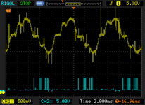
Blue line: hall sensor signal.
Yellow line: phase B current signal.
The next series of screenshots were taken with motor at different speeds, starting at motor low speed up to max speed.
I was expecting to have a sinusoidal current waveform... anyway, as we can see, there is a synchronization between both signals - and they need to be so we can have the motor best efficiency.


I didn't measured yet the lack of phase, but I know it changes with dynamic variables: motor current and motor speed. And fixed variables: motor coils resistance and inductance.

(in Shane Colton documentation)
For the screenshots, I think the algorithm can be like looking at current max or min value and will be the time where current vector I is - then I need to adjust the timing of motor voltage I already prepare, to displace the I vector 90 degres over rotor flux (yellow vector on the picture). Let's see if I can do it and have good results....

(in Shane Colton documentation)
Yellow line: phase B current signal.
The next series of screenshots were taken with motor at different speeds, starting at motor low speed up to max speed.
I was expecting to have a sinusoidal current waveform... anyway, as we can see, there is a synchronization between both signals - and they need to be so we can have the motor best efficiency.


I didn't measured yet the lack of phase, but I know it changes with dynamic variables: motor current and motor speed. And fixed variables: motor coils resistance and inductance.

(in Shane Colton documentation)
For the screenshots, I think the algorithm can be like looking at current max or min value and will be the time where current vector I is - then I need to adjust the timing of motor voltage I already prepare, to displace the I vector 90 degres over rotor flux (yellow vector on the picture). Let's see if I can do it and have good results....

(in Shane Colton documentation)


