stancecoke
1 MW
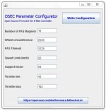
I just made a little java tool for setting up the main parameters. It edits the config.h-file and starts the compiling process. I think I have to read about the command-line flash tool from ST to add the flashing process to the batch-file ") . The tool needs Java Runtime.
. The tool needs Java Runtime.
In this way any user without progamming skills can use our firmware project
Regards
stancecoke
. The tool needs Java Runtime.In this way any user without progamming skills can use our firmware project
Regards
stancecoke