casainho
10 GW
- Joined
- Feb 14, 2011
- Messages
- 6,058
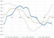
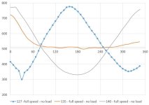
I am being thinking in what I learned when developing the FOC firmware for the electric unicycle and try to adapt to this Kunteng STM8 controllers with much more limited hardware.stancecoke said:I've built a test bench for the comparison of the different working modes, to see how important the correction angle is in real life
In FOC, the algorithm take as input the 2 phase currents and motor rotor position (from hall sensor for instance) and outputs 2 different current values: Id and Iq. On Kunteng STM8 controllers, there is only the signal of 1 phase current and it does not have processing power available to the FOC algorithm.
Id current is the current/torque we want to apply to the motor and so we control PWM duty_cycle value in a way to have the desired Id current in amps.
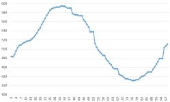
On Kunteng STM8 controllers, I think we can simple read the max value of the sinewave phase B current and multiply with a factor to have the average current value ----> Id current.
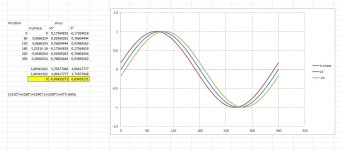
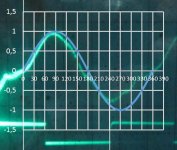
Iq current is a vector with 90º displacement compared to Id vector. Iq must be controlled to be 0 and so the motor will have max efficiency. To control Iq to be 0 we need to adjust the phase/angle voltage that we apply to the motor phase wires.
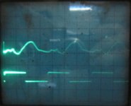
On Kunteng STM8 controllers, I think we need to find the offset/gap of the current sinewave compared to the motor rotor position (hall sensor signal). I need to find a working and robust algorithm to measure this offset/gap of the current sinewave!!! Any ideas??


