KT motor controllers -- Flexible OpenSource firmware for BMSBattery S/Kunteng KT motor controllers (0.25kW up to 5kW)

Just take an amp-meter and measure the drawn current under load, then calculate back the Cal_a value. Perhaps at different loads to get an averaged value.

regards
stancecoke
  • Battery Current cal a: Factor a in the calibration function. ADC value = calA * Battery current + calB. calB is measured automatically at starup. Required for internal calculation of the current from the 10bit ADC value. For a 6FET and 12FET controller the value has to be something around 100, for the 18FET about 50.\

Does this mean the ADC value has to be 100? That would be the only way to calculate back the calA with the battery current and calB. Is battery current the maximum battery current seen delivered by the battery?
 
Hi! I recently upgraded my hub motor from a unknown 250w motor to a 500w Mxus XF15c. Ran the old one at 300 watts, and I'm using a 6 FET KT36/48SVPRD-ffF10L controller. Setting it to run at 10a, I get some jerkiness at startup. Around 10-15 km/h it ramps up to 300w, then drops to 150w, then goes up again. I believe it has to do with the gain P and I values, and fiddling around with them has improved things a bit, but not completely solved it.

The documentation states that lower values P reduces risk of oscillating and lower I values runs smoother into the setpoint. But what are considered "lower values"?

The values I'm using are:
Battery current max: 100
Phase current max: 200
Battery current cal a: 100
Gain P: 0.3 (default 0.5)
Gain I: 0.06 (default 0.1)
It's a long time since I played around with KT controllers and o/s fw and, in truth, I've forgotten most of it now, but I do recall that 'phase current max' seemed to need a surprisingly high setting, try increasing this to 300-400 and see what happens. Other than this I can't help I'm afraid.
 
It's a long time since I played around with KT controllers and o/s fw and, in truth, I've forgotten most of it now, but I do recall that 'phase current max' seemed to need a surprisingly high setting, try increasing this to 300-400 and see what happens. Other than this I can't help I'm afraid.
Thanks for your reply. Weirdly enough, I tried lowering it to 150 earlier today, and it seems to have solved the problem. Don't understand why, but if it works, it works...
 
Hello,
Is it possible to use External Speed Sensor setting with 6 magnet (ticks) per revolution? I have motor G310 bafang, geared, give 6 pulses per turn. Preparing to flash controller. Where add number of pulses? Have someone config for this motor?
 
Hello,
Is it possible to use External Speed Sensor setting with 6 magnet (ticks) per revolution? I have motor G310 bafang, geared, give 6 pulses per turn. Preparing to flash controller. Where add number of pulses? Have someone config for this motor?
Yes, but you have to edit the source at change it somewhere. Instructions are hidden on one of the previous pages of this very long thread. Or I can take a look on my other computer later, where I have a patched version for my Bafang G60. You may also just be able to divide wheel circumference by 6 and get the same result, but I have not tried that.
 
i have osec running on 18 fet controller and i am using tsdz2 motor but i cant get the motor to work.
i have tried different hall and phase combinations but cant get it to run well, in one combination the motor spins but like pulsing when apply throttle.
maybe the motor hall angles are wrong?
Any help?
Näyttökuva 2024-07-28 160209.png
 
Yes, but you have to edit the source at change it somewhere. Instructions are hidden on one of the previous pages of this very long thread. Or I can take a look on my other computer later, where I have a patched version for my Bafang G60. You may also just be able to divide wheel circumference by 6 and get the same result, but I have not tried that.
Looks complicated, of course please write patched function, if you have minute. Will other settings work from java config?
 
i have osec running on 18 fet controller and i am using tsdz2 motor but i cant get the motor to work.
i have tried different hall and phase combinations but cant get it to run well, in one combination the motor spins but like pulsing when apply throttle.
maybe the motor hall angles are wrong?
Any help?
View attachment 357220
Great to see you were able to do the first steps. I only have experience with direct drive hub motors, so to me the motor specific angle and correction angle look completely wrong. But i don’t know what are the correct angles for a mid drive. Have you tried clicking some of the presets to try those angles as a first effort? Just be sure to adjust the current settings before you give it a try.

Some observations regarding your other settings:
- throttle min looks a bit low for a first try; I always start with 50 and work my way down after everything is ok.
- batt current cal a looks way too high for an 18 fet. Without shunt mod, i would expect something in the 21 - 23 range.
- in that case, battery current is now set to 100/23*10=43 amps, which is ok for a first try. (With proper mods to traces/bus bars+cooling, these 18 fets can take up to 200 battery amps! But only for heavily modified versions..).
- did you do a hardware lvc mod? If you didn’t, the voltage calibration will always be wrong because you cannot set a high enough value. Just set it to 100 and modify the undervoltage and overvoltage accordingly, for example 100 as undervoltage and 150 as overvoltage. If you want real voltages in the app, i would recommend replacing the 39k lvc resistor by a 25k one and setting the voltage calibration to 89. Alternatively, you can solder a 70k resistor in parallel to the existing 39k resistor (I normally do this, with a small blue variable potentiometer, set to 70k and manually fine tuned to the correct voltage).
- phase current looks a bit low, but this is ok for initial testing. Without modifications I would estimate that 150 phase amps should be fine . So with the default shunt (21-23 correction value) this would be a value of 345. With proper strengthening of the traces and bus bars these 18 fets can easily handle 300 phase amps. This would imply a value of over 600 in the app. But don’t start with such high values! Start slow and learn the firmware and controller.
- you have not enabled off road mode, and so without pas your speed is limited to 6 km/h and your motor will stop as soon as this speed is reached (jerkiness). If you increase the value of 6 to something like 25, your motor gets a chance to spin up. With a 72v battery and optimally tuned controller and hub motor, these controllers can easily reach over 80 km/h (>50 mph).

I hope this helps to get you started? I still love these 18 fet kt controllers, even compared to sabvoton, votol and other modern controllers. Because of the high power (>15 kw max), compactness and low weight (1 kg). Perfect for a very fast mtb!
 
Yes, but you have to edit the source at change it somewhere. Instructions are hidden on one of the previous pages of this very long thread. Or I can take a look on my other computer later, where I have a patched version for my Bafang G60. You may also just be able to divide wheel circumference by 6 and get the same result, but I have not tried that.
If i recall correctly, you can adjust the value of ‘gear ratio’ in the java config to achieve what you want? Just click some of the presets to see what are common values?
 
  • Battery Current cal a: Factor a in the calibration function. ADC value = calA * Battery current + calB. calB is measured automatically at starup. Required for internal calculation of the current from the 10bit ADC value. For a 6FET and 12FET controller the value has to be something around 100, for the 18FET about 50.\

Does this mean the ADC value has to be 100? That would be the only way to calculate back the calA with the battery current and calB. Is battery current the maximum battery current seen delivered by the battery?
I would always advise to do a calibration for each individual controller, because that is the only way to know for sure that the amp settings that you enter in the configuration correspond to what is happening in real life. And so this is also the only way to get to the absolute maximum of what your mosfets can handle (set the controller exactly at the limit that you think is still safe).

The easiest way to calibrate this value, is to use a bms that monitors the drawn battery amps, such as an ANT bms. The Bluosec Bluetooth app can
Show the actual and maximum battery amps that you have drawn.
Then you just compare the amps reported by bluosec to the ‘real’ amps as reported by your bms, and adjust the cal a correction if necessary. If the amps reported by bluosec are too high compared to the real amps, you should increase the cal a value and vice versa (if i recall correctly; just check and experiment will small changes). So, a smaller cal a value results in a larger maximum current for the same current settings. And the correct cal a is completely determined by your hardware resistance of your shunt.

So for my 18 fet controllers i normally perform a shunt mod (solder a piece of resistance wire: (manganese alloy) in parallel to the existing shunt), in order to decrease cal a to a value of 10. In that way, the maximum battery current that i can set is 255/10*10=255 amps, which is just a tad more than the maximum that i use (210 battery amps in java, 300 phase amps)
 
Noise issue in my case is due to processor ADC, and not due to CSA or hand soldering quality.

Attached phase current waveform with different processors on the same board.

Phase current (for 180 degrees) at a certain load & speed as seen by the processor 1 in uP1.png. This one doesn't have resistance at coasting, current waveform is relatively smooth (for the issue at hand, ignore the current not being a proper sinewave, hall interpolation inaccuracy is causing it, it needs improvement)

For the same condition, phase current as seen by processor 2 is in uP2.png. This have resistance at coasting, it have a lot of noise in the current.

Note that current waveform observed in scope is similar (w.r.t noise) in both the cases, i.e. they were smooth.

In my case, processor is STM32F103, both were clones, verified by reading processor JTAG id. On KT, IIUC, processor is STM8.

So there is a possibility that the KT STM processor (clone?) is the culprit for resistance at coasting.
Very interesting! As I am more of a hardware guy instead of firmware tuning, I have made many versions of the 18 fet kt controller already. This also includes ones with a different mcu. As caisiunho suggested in one of the first pages, i have replaced the mcu in one of the controllers with a faster calculating one (STM8S208CBT6, 24 mhz and more memory ). Unfortunately, i also burned the mosfets by using Andrea’s fork (no disrespect; i highly applaud any efforts for the firmware. But i will stick with stancecoke’s firmware because that has always worked great for me with instant cut of power when engaging regen braking). So i will rebuild the controller with this faster mcu.

Also @stancecoke:
What benefits can we get from using this faster mcu? Do i need to adjust the dead time between mosfet switching to account for the faster calculation speed? Or is (dead) time in the firmware independent of the frequency that the mcu is running at?

I think it would be cool if we could ‘unlock’ additional precision or features by just replacing the mcu by a better version (with heat gun and steady hands + a lot of patience..)?
 
I recently acquired a hub motor kit that came with one of these controllers. However, when I open the controller, The pin points don't seem to match up and I want to be sure I'm doing this correctly. Compared to the wiki that shows the pictures, I can identify two out of 5 potential points where the wires should go, but the rest don't seem to match up. The pin points are labeled "GND,ABS,RET,5V,TX,RX". In the original photos, I see there are 4 soldered to 4 points, but I can only make out two of them based on the notes as the images are blurry(GND, 5v). Based on the available pin points, where might the other two wires go? Please assist, anyone.
 

Attachments

  • pic 1.jpg
    pic 1.jpg
    2.6 MB · Views: 22
  • pic 2.jpg
    pic 2.jpg
    4.8 MB · Views: 23
I recently acquired a hub motor kit that came with one of these controllers. However, when I open the controller, The pin points don't seem to match up and I want to be sure I'm doing this correctly. Compared to the wiki that shows the pictures, I can identify two out of 5 potential points where the wires should go, but the rest don't seem to match up. The pin points are labeled "GND,ABS,RET,5V,TX,RX". In the original photos, I see there are 4 soldered to 4 points, but I can only make out two of them based on the notes as the images are blurry(GND, 5v). Based on the available pin points, where might the other two wires go? Please assist, anyone.
I don't think that´s a Kunteng controller. The layout is very different from the ones I have taken apart. What does it say on the outside?
 
I don't think that´s a Kunteng controller. The layout is very different from the ones I have taken apart. What does it say on the outside?
You're probably right. It came with a csc kit. I assumed they were all more or less the same. Im using a vesc based controller now so all is good.
 
Hello, is it possible to place a temperature sensor in the engine and connect it to the system to have the temperature displayed on the lcd3 screen?

Is it preferable to use a thermistor or a sensor such as the lm335?

Thanks
 
Hello, is it possible to place a temperature sensor in the engine and connect it to the system to have the temperature displayed on the lcd3 screen?

Is it preferable to use a thermistor or a sensor such as the lm335?

Thanks
I would also be interested in this. In the Bluosec version it works flawlessly; you can mount a 10k thermistor in the motor (in hub motors: often there is already one mounted. Sometimes it’s a kty; replace it by a 10k thermistor then), route the signal wire (white) to x4 input to controller, and fine tune the calibration in the app. But i don’t know what code to change in the ktlcd3 version; it would be great to be able to show the temp on the display. Even better: it would be awesome if someone could implement an amps/duty cycle reduction algorithm if the temp goes over a threshold value; e.g. 110 degrees centigrade. Is anyone capable and interested in implementing this code?
 
Question about excessive heat/losses during idle:

I am trying to (re)build an ultimate version of the 18 fet controller running at 96v (110v peak) and hopefully 200 battery amps with 300 phase amps. The goal is to get close to 20kW of battery power. I already have these 18 fet kt controllers running flawlessly at 15 kW (using 100v fets such as the irfb4110, and 200a of sustained battery amps with 300 phase amps). In this new iteration I use the toshiba tk72e12n1 fets (from china; not sure if they are genuine yet..). I had to rebuild the controller because the fets blew using Andrea’s firmware (no hard feelings; i applaud his efforts) when activating regen. Now, with fets replaced and using stancecokes’ original firmware (with a lot of floating point calculations?), it does boot properly at all voltages up to 110v. (Yeah! A victory in itself!)

But i have the following problem: at 84v, the fets are nice and cool and the controller only uses 0,09a^2*8,1ohm(shunt for testing)=0.07watt switching loss.

But at 110v, the controller uses 3watt of battery power and gets hot slowly.

My guess is that this loss must be switching losses due to increased gate charge @110v. I guess that the mosfets are harder to drive @110v.

To mitigate this, I tried the following measures:

- increased driving voltage (dc dc buck converter) from 12v to 16,7v -> this increased the losses at 84v (driver losses?), but slightly decreased the losses at 110v (less time spent at miller plateau?).
- increased dead time from 1 us to 1.5us. This did not change the heat losses at all.

Does anyone have suggestions how to further reduce the idle losses? It just gets too warm at idle the way it is now. I was thinking of:
1. driver resistance-> not feasible due to no space to work
2. Further increase driver voltage to say 19v
3. Use ‘torque from x4’ master branch for faster calculation of the 0-point for pwm. (Less error?)
4. Use the experimental pwm off at idle option -> this should work fine, but first i want to reduce switching losses.

Is there a setting in the firmware that can be adjusted to increase the precision of the ‘idle pwm point’? At 110v, any microscopic (allowed) error in the amps reading would result in a lot of heat loss, so my hope is that some optimization of the idle set point would be possible and useful here?

Any suggestions would be helpful, I just don’t want to try things without good reason, because there’s a lot of work in this frankenstrein controller already;)!

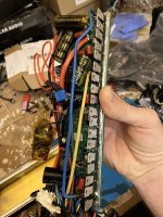
If the fets are the problem, i would build a version with aot2500l (150v) instead, but those have twice the rds on. So i would rather stick with the tk72e12n1.

IMG_9970.jpegIMG_9970.jpeg
 

Attachments

  • IMG_0050.jpeg
    IMG_0050.jpeg
    2.1 MB · Views: 5
  • IMG_0261.jpeg
    IMG_0261.jpeg
    1.8 MB · Views: 5
  • IMG_0262.jpeg
    IMG_0262.jpeg
    2 MB · Views: 4
  • IMG_0241.jpeg
    IMG_0241.jpeg
    2.1 MB · Views: 8
  • IMG_0242.jpeg
    IMG_0242.jpeg
    1.2 MB · Views: 8
  • IMG_0139.jpeg
    IMG_0139.jpeg
    104.9 KB · Views: 9
  • IMG_0038.jpeg
    IMG_0038.jpeg
    2 MB · Views: 8
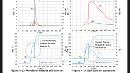
It could also be limitations in the board layout, leading to excessive dV/dt current and consequent self-turn on of one of the bridges? Need to do some more testing i guess…
 

Attachments

  • IMG_0282.png
    IMG_0282.png
    308.6 KB · Views: 2
  • IMG_0284.png
    IMG_0284.png
    241.7 KB · Views: 2
I’ll just keep talking to myself; maybe it is of use to someone else 😂:

Ok, so the solution seems to be in a combination of steps, most of which are firmware related:

1. I started at some 6v voltage drop over the 8.1ohm shunt resistor (testing purposes). Ie a heat loss of 4.6w.
2. Increasing the gate driver voltage (buck converter voltage) from 12 to 16.8v reduced the voltage drop to some 5v.
3. Switching from stancecoke firmware to torque from x4 firmware seemed to have a slightly positive effect as well.
4. Reducing the zero amps limit in main.h reduced the voltage drop to some 2.4v
5. Increasing the averaging time in adc.c for cal b by at least a factor of 2 seemed to help slightly in reducing voltage drop, maybe 0.2v
6. Enabling pwm off @coast further reduced the power consumption during idle by a factor of 10 , resulting in a voltage drop of 0.215v over the 8.1ohm resistor.

Conclusion: so far the hardware still seems fine to handle the 120v mosfets; the tolerances for 0 amps in the firmware seem to be the main reason for excessive heat generation during idle.

Now, with ‘pwm off @ coast’ enabled, the heat loss during idle has become negligible.

Next steps: improving the cooling by filling the controller with parrAfin oil and testing the controller on a ‘bicycle’ with a mxus 4t 45mm hub motor (of course with ferrofluid and custom heat sinks..). In search of the 20 kW target from these cheap aliexpress 18 fet controllers!

Future dream: a 40 kW (dual 20kW 18 fet kt controller) setup with 6 phase monster motor 😝
 

Attachments

  • IMG_0298.jpeg
    IMG_0298.jpeg
    5.5 MB · Views: 5
  • IMG_0296.jpeg
    IMG_0296.jpeg
    8.5 MB · Views: 5
  • IMG_0295.jpeg
    IMG_0295.jpeg
    1.8 MB · Views: 3
  • IMG_0294.jpeg
    IMG_0294.jpeg
    1.8 MB · Views: 1
  • IMG_0259.jpeg
    IMG_0259.jpeg
    2 MB · Views: 1
  • IMG_0124.jpeg
    IMG_0124.jpeg
    1.7 MB · Views: 5
the tolerances for 0 amps in the firmware seem to be the main reason for excessive heat generation during idle.
Have you checked/adapted the PWM deadtime? I guess, this is the main source of heat generation. Especially if you have to drive many MOSFETs in parallel, you'll need more deadtime to avoid shorts from Highside MOSFETs to Lowside MOSFETs

regards
stancecoke

https://github.com/stancecoke/BMSBa...52ea632542cdaf9870063e05f79928cae2/pwm.c#L102

- increased dead time from 1 us to 1.5us. This did not change the heat losses at all.
Ah, I see you have tried it already. But have you read the reference manual for the processor carefully? The deadtime calculation is quite tricky ;)
Have you used much higher values also? In this cases it is often helpful to vary the parameter by *10 or /10 to see a clear effect.
 
Last edited:
Have you checked/adapted the PWM deadtime? I guess, this is the main source of heat generation. Especially if you have to drive many MOSFETs in parallel, you'll need more deadtime to avoid shorts from Highside MOSFETs to Lowside MOSFETs

regards
stancecoke

https://github.com/stancecoke/BMSBa...52ea632542cdaf9870063e05f79928cae2/pwm.c#L102


Ah, I see you have tried it already. But have you read the reference manual for the processor carefully? The deadtime calculation is quite tricky ;)
Have you used much higher values also? In this cases it is often helpful to vary the parameter by *10 or /10 to see a clear effect.
Thank you for your suggestions Stancecoke! Great to see that you’re still visiting this forum. Your work on this firmware is still being loved and appreciated.

I will try a deadtime of 10 us then, to see if it makes any difference to 1 us. My gut feeling would say 3 us is already a lot, but i’m neither an electrical engineer nor a mosfet expert so i will just follow your suggestion to see if it makes any difference. So just to be clear: this same controller with 3 paralleled fets has barely any heat loss at idle at 84v, but at 110v the losses increase by a factor of 8 (after the other optimizations mentioned before).

Ehmm and no, i did not read any processor manual (for the stm processor you mean?).

I just changed the value of 16 (1us/62.5ns = 16) for the dead time to 24 (1.5us). And now i will try 160 for 10 us, or am i missing something else here?
 
See the reference manual:
1733861280671.png

to be honest, I don't know, how the Standard Peripheral Library handles the values in the TIM1_BDTRConfig command. :)

regards
stancecoke
 
Back
Top