Ktronik's "The Blinder" LED Tail Light Project

Any 100V - 240V AC switching power supply can take >50V DC as input and perform per specification.

Technical Reference Section

But dont think of big supplies... think of all the tiny little wall warts you have round the house:

9V 2A DC-DC

Some times it takes a little tinkering - but this is the hot ticket for a dead cheap (free) DC-DC converter to run right off the pack.
May not work for you 48V guys... but I run 24S lipo so it is perfect.

I also use notebook power adapters to simulate a 12V source (cigarette lighter) on my bike. I have a 15V 5A tiny little brick that can run anything from my notebook to HID headlights to any kind of car adapter you can think of.

Sweet eh?

Give it a try. You can see some of my test results in the tech section.

-methods
 
Thanks Methods,

Your 9V 2A DC-DC link has expired on eBay. Reading the original thread from Fechter http://endless-sphere.com/forums/viewtopic.php?f=16&t=2264&hilit=switching, I found this over on allelectronics.com which seems to fit the bill for "The Blinder". Variable outputs of 3 / 4.5 / 6 / 7.5 / 9 or 12 Vdc. Input is unknown but is probably 100-240V. Price is $9.95.

http://www.allelectronics.com/make-a-store/item/PS-10/1-AMP-SWITCHING-POWER-SUPPLY-w/-SELECTABLE-OUTPUT/-/1.html

From what I've read on the driver board, it won't take more than 5V input and these types of power supplies tend to run a bit high. So the 3 should work fine, the 4.5V may or may not work and the higher voltages definitely won't.

Thanks again for the idea!
Ambrose
 
Another place to look is in your box-o-wall-warts. I've got lots of 'em laying around. There has to be something there that will work!

Ambrose
 
Yep! All Electronics is a great store. I buy all sorts of stuff there and I overlooked that on you found. I will pick one up and test it.

It can be hit and miss though depending on the design. . .
One thing to note: Some times you need to watch the polarity coming in! It appears that some of the switchers only use a half bridge rectum-fryer at the front end so if you are having trouble, switch the input polarity.
This happened to me with a dell power supply. I cant say for sure what the cause was, but the input was clearly directional from a DC perspective.

It would be good to load test whatever you have too before going to a bunch of work wiring it in.

Please post your test results and I will shuttle them over to the Technical Reference thread for others to learn from.

-methods
 
ambroseliao said:
Thanks Methods,


From what I've read on the driver board, it won't take more than 5V input and these types of power supplies tend to run a bit high. So the 3 should work fine, the 4.5V may or may not work and the higher voltages definitely won't.

Thanks again for the idea!
Ambrose

Its a LDO type reg so 6v ok...but as any 'over head' is burnt off in heat, going too high will kick in the thermal cut...time to move forward

This lite was made to a price point & originally, was made to use the batt pack I had made for her Mshine light, after the driver had died...it was for a customer that wanted to keep the costs down... so the power input dictated the driver...

Power input should always dictate driver selection...with so many cheap drivers on offer, you should not worry about using the cheap liner LDO driver & chose a driver better suited to your voltage app.

That way you will open your options to power input...I know that Taskled.com is now making E-bike LED drivers... Ok they don't go high enough for guys like Methods, but with a wall wort in front you have a easy fix...

K
 
methods said:
Yep! All Electronics is a great store.
I even got my tires from them. :)

I dont' know why it didn't occur to me to try wallwarts on DC; I already have a couple of modular-cage PC power supplies that are labelled as ~48VDC in (but actually have all the parts inside to run off AC 115V, just not an AC style plug).

Since I have a bajillion wallwarts of all sorts of voltages, especially cellphone chargers and similar (most with around 4.5V output), that should be perfect, if I can get them to run on *less* than 48V.

Right now, all I have is 36V of lead, and no good place to put a fourth (and have to mod the controller a bit for 48V) yet.

Hmm....
 
(also posted this in the other recent bike light thread this one came from):

It's been mentioned that some AC power supplies might work from 48-50VDC and up, and be able to power these kinds of lights from your traction packs, when looking to convert your pack's high voltage down to something some of the low-voltage LED driver boards like the one on Dealextreme can handle.

I may have found a way to power them from lower voltage traction packs pretty easily, via a cheap (free, actually) source of DC-DC converters, in old celphone chargers and other portable-device AC adapters.

I started going thru my collection of ac adapters, including a couple acquired from Freecycle today, and found a couple of Samsung celphone chargers (TAD137VSE) that output "5.0V @ 0.7A" for "100-240VAC @ 0.7A" which also output the regulated supply at as low as 23VDC input. I'm sure the current draw would be higher at the lower voltage, but I didn't test it at it's full output, only with a 1Kohm load on it (~5mA), which drew pretty much nothing on the source side according to the Sorenson's ammeter.

I tested by hooking the AC input of the charger to the DC output of my Sorenson 0-60VDC adjustable linear bench power supply, the 1Kohm load to the + and - output terminals of the charger, and the DMM on VDC across the resistor. Adjusting the Sorenson's output from 0V upward resulted in output from the charger around 3.5-4VDC starting at about 18VDC input from the Sorenson, swinging up to 5.14VDC output at a 23VDC input, stable at that voltage all the way to the 62VDC max output of the Sorenson.

It is stable at 5.14V with that load or no load; might regulate better to 5.0V at a higher load. One diode in series with it should drop it enough to not worry about for the LED boards on the bike lights.

It's around 3.5W output capability at 5V, about 3.1W with the diode dropping almost half a watt across it at full load. So depending on what the LEDs draw, one of these might easily supply that LED board. Two paralleled would work if one won't, and they're quite small and light, even if left in the original little wallwart cases. If used like that, the long lower-voltage wire from it could be run to the light, rather than the higher full-pack voltage, making it safer if a wire were ever shorted somehow.

Alternately, they could be built into the lights' housings, and just run full pack voltage there (with a fuse or micro-breaker at the pack end).

I have a bunch of others not yet tested that range from 4.5V to 6.0V outputs, and from 100mA to over 1A output capabilities.

Some of the ones tested wont' start until they reach 50V or more. The Samsungs were the first ones I found that work at such a low voltage.
 
I finally foud a new minutes to put together my "Blinder." The LEDs couldn't be easier to solder together. They have large solder pads and they are clearly marked. That went very well.

I then tried to solder the power and LED leads to the driver board. That's when I ran into a problem. The leg on Q3 is so tiny that I can't solder the battery and LED negative terminal to it. The problem is the actual soldering of the wires to the driver chip. This driver board has chips with very small legs that requires an extremely small tipped soldering irons and perhaps stand mounted magnifying glasses.

Does anyone have a suggestion on how to solder these tiny wires to tiny boards?

Thanks,
Ambrose
 
ambroseliao said:
I finally foud a new minutes to put together my "Blinder." The LEDs couldn't be easier to solder together. They have large solder pads and they are clearly marked. That went very well.

I then tried to solder the power and LED leads to the driver board. That's when I ran into a problem. The leg on Q3 is so tiny that I can't solder the battery and LED negative terminal to it. The problem is the actual soldering of the wires to the driver chip. This driver board has chips with very small legs that requires an extremely small tipped soldering irons and perhaps stand mounted magnifying glasses.

Does anyone have a suggestion on how to solder these tiny wires to tiny boards?

Thanks,
Ambrose

Mate, have another look @ the pics as you don't have to solder everything to the 7135's... you should not have to solder anything to it, there should be 'pads' for everything...worse comes to worse you just solder to the LED output...

so BATT + goes to big pad on driver, same wire then to LED +
LED- goes to (@ worse, the LED output on 7135)
BATT- & GND on the board are the same, only one wire is needed.

3 wires only one at worse, to the 7135 chip...buzz around with your meter, you should find a pad that is connected

K

...
 
Thanks Ktronik,

I did buzz the pad right next to the chip which didn't work, but obviously missed the point of the big pads right next to it marked "Q1". I'll try again tonight. It was very late! :)

I see that Kaidomain has the same or very similar chip only with soldered leads. http://www.kaidomain.com/ProductDetails.aspx?ProductId=1677
Is this identical in function to the DX 7135 driver? This might be a lot easier for those who are soldering iron challenged!

Thanks,
Ambrose
 
I took a look at the diagrams that folks had posted over at CPF and figured out where the wire should be soldered.

It is now working and it is indeed as Ktronik said, The Blinder!

http://picasaweb.google.com/ambroseliao/TheBlinderWorks#5395631406943924498

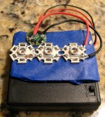
Here's The Blinder on top of the 4xAAA battery case from RS. I need to figure out how to mount it into a case of some sort. The LEDs are on some blue masking tape to hold them in place while I soldered things.

The Blinder.jpg

Thanks again, Ktronik for your inspiration and support!
 
cool....

I am totally building a Blinder.
I want mine to be so bright that cars crash, other cyclists steer into the bushes, babies cry, winos go into epileptic seizure, and new-age hippies call the police to report that the aliens have landed.

Good job!

-methods
 
Methy- Doing coral lighting, I've been playing with some LEDs that make Cree XR-E's, and even MC-Es and P7's look like a joke. Cree XP-G's are still a decent emmiter for lower output needs though.


SST-120. It's your daddy.
spec sheet:

http://www.luminus.com/stuff/contentmgr/files/0/5c9bb07b5d6848a0f7368f2716e49fa6/pdf/pds_001226_cbt_120_rev02.pdf

Buy this, and you will have airplanes trying to land on your back.

The Cree red's are going to be giving you 40-60lm at most. This MoFo delivers 1400lm when pulsed at 50%, which is perfect for your appliction.

Here's where to get them. I normally buy the blue ones. They have 1 red in stock, it says to ask for quote, but I can tell you the blue's go for around $110 each. Not bad at all considdering you are replacing the light of 25-30 cree XR leds in 1 neat little package just begging to be thermal epoxied to the frame of the bike.

http://avnetexpress.avnet.com/store/em/EMController/LED/Luminus-Devices/CBT-120-R-C11-BJ-R5/_/A-8787198/An-0/R-8787198?action=part&catalogId=500201&langId=-1&storeId=500201&listIndex=0&yposition=157

For forward lighting, the XP-G's from Cree are really a pleasure to work with for medium light output needs. Much better than working with P7s or MC-Es. Here is a guy that made nice bike light with some XP-Gs.
http://forums.mtbr.com/showpost.php?p=6198611&postcount=28
 
Lol, I just realized that at 30amps, that LED draws more current than some folks E-bike motors. lol Good thing it's only at 2.6v.
 
Awesome beam shots
I love it when someone shows 5 or 6 beam shots in the woods of progressively better setups.... I usually look the the first one and think "wow - great headlight!"
Then by the end of the sting of beam shots it is more like "Wow, why is that guy doing beam shots at noon?" :p

-methods
 
I am currently using the brightest tail light that I could find, the Planet Bike Blinky Superflash. It' has one 1/2W LED with 2 smaller LEDs. It's fine, however, it uses a lens to focus the main light into a tight narrow pattern that shoots directly back. I have it attached to the back of my helmet. if you move your head, the light essentially disappears. The Blinder is much more omnidirectional and much, much brighter.

I made another video to show the difference. I start by showing the Superflash, then pan to the Blinder. Then I show both side by side. You can obviously see which one is brighter.

http://picasaweb.google.com/ambroseliao/TheBlinderWorks#5396026286161943826

Ambrose
 
ambroseliao said:
I took a look at the diagrams that folks had posted over at CPF and figured out where the wire should be soldered.

It is now working and it is indeed as Ktronik said, The Blinder!

http://picasaweb.google.com/ambroseliao/TheBlinderWorks#5395631406943924498

Here's The Blinder on top of the 4xAAA battery case from RS. I need to figure out how to mount it into a case of some sort. The LEDs are on some blue masking tape to hold them in place while I soldered things.


Thanks again, Ktronik for your inspiration and support!

Good work for getting it done...

err, not meaning to be rude, but a little more heat on the soldering iron is needed, apply solder to the wires first, then the pad, then heat together... from the look @ the pic, you can use much smaller wires as it a tiny amount of current you are using... & yep 70 deg viewing angle for cree

Its hard to think that this cheap cr*py light is getting so much attention, I spend hours making my CNC lights, which can be build in RED, but you guys like this one...the one that I spend 5min designing for some chick...dude its chicks light!! Now methods, you need to make a blinder out of XPE (red) triple MCPCB's, for the same 20mm OD you can have 3 LED... so for same size you would have 9 LEDs!! Now that's more like you & your high powered E-bikes... :D
 
K-tronic- You need to check out SST-90's and SST-120's. Not quite the lm/w of the Cree stuff, but very close, and so much more output. You would need a whole board covered in XP-E's to equal a single SST-120. :)
 
Yeah, you're right about the soldering job I did, but it works! :)

I need to melt the solder better so it flows. Right now, they almost look like cold solder joints! I'll use thinner wire for the final.

I don't know if you really want to go any brighter than the Blinder right now. It lives up to it's name, however, any brighter and I think you will start pissing off drivers behind you rather than just warning them to stay away. Anything brighter could literally blind the driver, at least temporarily, which isn't good! You or someone else could be hit

Ambrose
 
Make sure your solder doesn't say "lead free" on it... If it does, chuck it in the garbage and go get some real solder. It will be the best thing you ever did towards making reliable electronics.
 
liveforphysics said:
K-tronic- You need to check out SST-90's and SST-120's. Not quite the lm/w of the Cree stuff, but very close, and so much more output. You would need a whole board covered in XP-E's to equal a single SST-120. :)


Yes the SST's look great & will make a good light, but as they are on the same die, I can't mix the tints as easy...in OZ we have lots of browns, so the mixed tints make good sence down under, it helps bring out the colour on the ride...

running the bigger die (SSCP7/MCE/SST's) normally means you need a bigger dia optic/reflector, to get your hotspot back...35mm+

so if your after a small 20mm dia optic light, then XPE/XPG is a good option...

K
 
ktronik said:
Now methods, you need to make a blinder out of XPE (red) triple MCPCB's, for the same 20mm OD you can have 3 LED... so for same size you would have 9 LEDs!! Now that's more like you & your high powered E-bikes... :D


If you give me links to the LED, Board, and Driver I will order them right now. :p
I have not had time to hack an LED yet so I am still foggy on the who/what/where for the parts.
Every time I decide to build something I get overwhelmed by the information.
I have a mental disorder that will not allow me to purchase a product if I dont know for sure that it is "The best" :roll:

So I guess I need the LED's, star boards, driver boards, lenses, - then i need to find a block of aluminum for a heat sink....

What I really want is a monster headlight that runs off of one of my DC-DC's

-methods
 
methods said:
ktronik said:
Now methods, you need to make a blinder out of XPE (red) triple MCPCB's, for the same 20mm OD you can have 3 LED... so for same size you would have 9 LEDs!! Now that's more like you & your high powered E-bikes... :D


If you give me links to the LED, Board, and Driver I will order them right now. :p
I have not had time to hack an LED yet so I am still foggy on the who/what/where for the parts.
Every time I decide to build something I get overwhelmed by the information.
I have a mental disorder that will not allow me to purchase a product if I dont know for sure that it is "The best" :roll:

So I guess I need the LED's, star boards, driver boards, lenses, - then i need to find a block of aluminum for a heat sink....

What I really want is a monster headlight that runs off of one of my DC-DC's

-methods

Start with a monster headlite...then move on to a back light...

start with the housing then see how you can fill it...

For very basic housing, try a light like my UGGA range... housing avab if needed...

http://www.candlepowerforums.com/vb/showthread.php?t=194266

BUT rather than use single LEDs use a Mix of LEDs...

so XRE w 10deg optics (20mm OD) & a few XPG's triples (20mm) for the flood... you can mix & match a good few 1000lm with quite a small piece of channel...Its easy one you have a place to start...

not really a problem to run off your DC-DC...you well me your final voltage out of your reduced side & I will tell you how to drive it...

K
 
Back
Top