• Hello ES! We could use some help to get us past the finish line on building the new knowledgebase for the forum.
    Can you donate? Please see our fundraising page. Thank you!

Lebowski's motor controller IC, schematic & setup, new v2.A1

Lebowski said:
what you can do, disable throttle closed and motor standstill detection (both in the recovery menu). Then you can reset the controller on the fly and
have it apply power again after the reset, without having to wait for motor standstill or throttle closed. Then all you get is a short 'hickup'...
Yes, that was what I was planning to do, the recovery function is great 8)
 
Any tips for getting 2.1 to work? I'm unable to get the FOC motor inductance test to finish. I hear the tone, goes for about 2-3 seconds, then stops, the chip/serial freezes and I need to reset the controller.

My current sensors are way to big, got some new ones on the way. LEM 100A (300A) and 300A (600A). I currently have some 600A (+900A) sensors installed and only have 1.04mV/A resolution which is pretty poor, but these were the only sensors I had on hand.
 
zombiess said:
Any tips for getting 2.1 to work? I'm unable to get the FOC motor inductance test to finish. I hear the tone, goes for about 2-3 seconds, then stops, the chip/serial freezes and I need to reset the controller.

My current sensors are way to big, got some new ones on the way. LEM 100A (300A) and 300A (600A). I currently have some 600A (+900A) sensors installed and only have 1.04mV/A resolution which is pretty poor, but these were the only sensors I had on hand.
calibrate your current sensors first.

I also had the same problem you are describing. I had to fix the diode in mine to make it work.
 
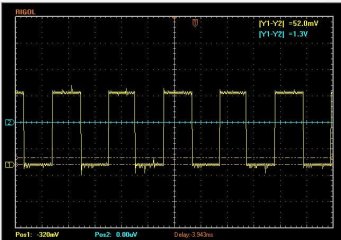
Lebowski. I spun the motor slower and got a cleaner calibration it give me confidence at 7
But I notice its still not smooth in sensored mode its a lot better but still rough. I will try putting a spacer under the sensor tomorrow to make it closer to the magnet and see if that helps.
Here is 2 tests and its off a bit from each other.
Edit... What if the noise is in the current sensors?? Remember there is no load on the motor and the current sensors are very low MV/A so a tinny bit of noise will make it think the timing is moving around...?

Although this still doesn't explain why the current sensors cause the motor to run rough if I try to run with them to a higher rpm...

What do you think? Anything else I can look at adjusting?

Oh and the noise is not bad either. The most I can see is .52v up from the floor (52mv is what its says but the probe was 10x)
 

Attachments

  • Capture halls.JPG
    Capture halls.JPG
    59.7 KB · Views: 3,747
  • Capture halls 2.JPG
    Capture halls 2.JPG
    56.6 KB · Views: 3,747
  • Capture Hlls.JPG
    Capture Hlls.JPG
    54 KB · Views: 3,747
I spaced the sensor closer to the magnet it was about 2.5mm to far way. And the measured deg for each step are more consistent. But its still really rough in sensored operation. What all can I look at to help this?
 
I'm still failing at getting a motor to run on the 2.21 chip. I don't know what the sensors config is supposed to look like when it's working. The chip will not complete the FOC test either, makes a tone, then locks up.

I'm using 300A sensors with a 6.25mV/A

Suggestions?
 
zombiess said:
I'm still failing at getting a motor to run on the 2.21 chip. I don't know what the sensors config is supposed to look like when it's working. The chip will not complete the FOC test either, makes a tone, then locks up.

I'm using 300A sensors with a 6.25mV/A

Suggestions?
Here is a link to the pictures of mine. After I thought about it I realized it might not matter if the current sensors are backwards will it? I guess if it turns on the + on the H bridge it would look for current to rise on the corresponding current sensor so yes.

Here is my sensor info part number CSLA2EN (950) amp
http://sensing.honeywell.com/index.php?ci_id=49794
You can see the side where you can see the triode gap is to the neg
 
I tried reversing the sensors, but it didn't make any difference. I must be missing something. I don't quite understand the setup of this version after reading the descriptions of each function. What should I expect from the current sensor calibration menus?

How can I tell if my values are in range? Any step by step setup instructions? Digging through threads for the occasional nugget of info is a bit tiring.
 
zombiess said:
I tried reversing the sensors, but it didn't make any difference. I must be missing something. I don't quite understand the setup of this version after reading the descriptions of each function. What should I expect from the current sensor calibration menus?

How can I tell if my values are in range? Any step by step setup instructions? Digging through threads for the occasional nugget of info is a bit tiring.
Once I fixed the short I soldered under a diode and tested my PWM at the gates mine was a breeze to set up to make a motor simply spin. I think something is just not right maybe a pin in the wrong spot... something assembled wrong or failed? Did you do a new design for this chip version?
My experience is you have to diagnose your own mistakes which actually makes it quite fun. :)

I had to calibrate the off set on the current sensors and I found the gain did not help me although I will revisit it now that I'm fixed up as I would like to figure out how to make it run smother in sensored operation.

You can call me ~ lunch time Jeremy If you need. I will be at work but that's a safer place then at home lmfao as its not only Valentines day but also Chantal's birthday :)
 
Arlo1 said:
I spaced the sensor closer to the magnet it was about 2.5mm to far way. And the measured deg for each step are more consistent. But its still really rough in sensored operation. What all can I look at to help this?
The hall sensors are only meant for starting the motor, so upto a few 100 erpm... if you go higher it will run rough, this has to do with the way the sensorless needs it to run in order to get the info it needs. Also, keep in mind that while its running on halls it is 6-stepping like a cheap china controller, so do not expect the smooth running like you get from when the controller is running sensorless (which is 256 stepping :D )

about the hall calibration, best is to run at a few 1000 erpm, so do not go slow and careful !
 
zombiess said:
I tried reversing the sensors, but it didn't make any difference. I must be missing something. I don't quite understand the setup of this version after reading the descriptions of each function. What should I expect from the current sensor calibration menus?

How can I tell if my values are in range? Any step by step setup instructions? Digging through threads for the occasional nugget of info is a bit tiring.
The current sensors cannot be reversed !!!!!!!!! and a few more for good measure !!!!!

Jeremy, just run the basic checs. Remove the motor. In the PWM menu, run the test signal with 5, 50 and 95 % and scope all outputs to make sure these are OK.
Necxt, with some car bulbs or something, run a decent amount of amps through the current sensors and make sure their polarity it correct and that the current sensor output signal makes sense (run the current both ways, make sure the sensor respons fits with the amount of amps your running through)

Typically calibration of the current sensors is not really necessary, especially the gain calibration is only necessary for HF...
 
I found my errors and corrected them. I had a cold solder joint on one of my gate resistors causing it to be intermittent. I had wiring issues as well, thought I had them all sorted out last night, but it turns out I didn't, easy fix.

I'm spinning a Cromotor now. I'll test out the sensitivity of different sensors next. I'm using some LEM HASS 100A (300A max) sensors at the moment.
 
zombiess said:
I found my errors and corrected them. I had a cold solder joint on one of my gate resistors causing it to be intermittent. I had wiring issues as well, thought I had them all sorted out last night, but it turns out I didn't, easy fix.

I'm spinning a Cromotor now. I'll test out the sensitivity of different sensors next. I'm using some LEM HASS 100A (300A max) sensors at the moment.


WOOOOOOT!!!
 
Does anyone have tips on tuning the loops and amplitude for drive mode 2 and 3? It's tough to tune without understanding the control method being used (I'm pretty sure it would take me a while to understand the math anyways). Got any suggestions on how to dial in the loops vs trial and error?

The motor is a Cromotor, 9.3 KV, 23 poles, 140uH inductance.

What happened to drive mode 1 in 2.21? I don't see it ever being used.
 
zombiess said:
Does anyone have tips on tuning the loops and amplitude for drive mode 2 and 3? It's tough to tune without understanding the control method being used (I'm pretty sure it would take me a while to understand the math anyways). Got any suggestions on how to dial in the loops vs trial and error?

The motor is a Cromotor, 9.3 KV, 23 poles, 140uH inductance.

What happened to drive mode 1 in 2.21? I don't see it ever being used.

Well, you can change the values from the autocompleted ones, I doubt though things will change much (unless you go and change values by a large amount)...

2.21 is the same as 2.30 , except it does not have the hall sensor part.

So, drive_1 indicates that it is in recovery. To play with recovery, you can disable both throttle closed and motor standstill checks in the recovery
menu. Then when you do a reset while the motor is running, it will go into recovery (so drive_1) to try to re-sync with the running motor.

The older versions you had conked out when something happened (detected by means of the error current) and it lost control, the newer ones will go
into recovery to re-sync so you can continue riding.
 
Lebowski.
What can I do for setting up the recovery better? I actually a combo of 2 problems I think. 1 when things go sideways I get a pass though enough to blow a fuse this seems to be something I need to sort on my end which I will post in my thread. But its during recovery when I have issues.

I'm trying to get things set up better but remember I don't have anything measuring the voltage of the phases or battery. Should it not come to a stop and stay put??
[youtube]Pyi5lSY0GvI[/youtube]
 
Hi Bas, I remember that we had similar effects as Arlo shows. The motor was turning without throttle. The primitive "solution" was to re-calibrate the throttle on the low-throttle setpoint with some mm hysteresis.
As you remember our setup worked quite nicely like this at low currents with the 74V power supply, but when we changed to the 50V battery and raised the current limit to 50A some things got worse. Both in sensored and sensorless mode we see strong hickups during startup and when switching from sensored drive_2 to sensorless drive_3. It was also not possible to exceed ~15A without interrupts.
I'm not sure if we fall back into recovery or into an error current shutdown. Is there a way to completely deactivate recovery? How can we raise the tolerance limits for testing purposes?
We fiddled around quite a lot with different settings and I think I understand them much better after your tips. But now we feel a bit helpless and don't know how to go on.
By the way: When staying in sensored mode by lifting d)e-rpm limit / d) transition erpm drive 2 -> 3: very high to 10'000 the controller delivers > 15A without problem.
Cheers, Marcel
 
Does the latest version have the ability to run in sensor mode only through the entire power range? This would be good for trouble shooting / testing.

I can't get a smooth no load light throttle start up. I'll often run into a locked rotor until it finally breaks free and the motor jumps up to speed and into FOC. If the rotor is in the right position it does a small rock and starts up smooth. This is the version prior to adding the hall sensors back so I'm all sensorless. I tried several setting for degrees and motor hz in menu L (I think it was L) as well as the current for positioning the rotor. Any hints on setting these correctly or does it only matter for being under load.

emmgee, do you have any idea where the faults might be coming from? Controllers tend to be pretty high in RFI/EM which could cause issues with the brain, especially if grounds are not isolated.

I haven't tested under load yet, so I have to wait and see if I have any issues with riding around / resets myself. The 1st version of the controller I used worked pretty well once I experimented with the loop tuning.
 
Arlo1 said:
Lebowski.
What can I do for setting up the recovery better? I actually a combo of 2 problems I think. 1 when things go sideways I get a pass though enough to blow a fuse this seems to be something I need to sort on my end which I will post in my thread. But its during recovery when I have issues.

I'm trying to get things set up better but remember I don't have anything measuring the voltage of the phases or battery. Should it not come to a stop and stay put??
It shouldn't be turning when the throttle is closed. And looking at the video, is it rotating when doing recovery ? It all looks pretty
strange... Did you change something to the throttle ? Maybe a hall sensor throttle is not radiomatic, then a change in the 5V supply
may influence throttle readings.

can you post the HEX dump of the settings ?
 
emmgee said:
Hi Bas, I remember that we had similar effects as Arlo shows. The motor was turning without throttle. The primitive "solution" was to re-calibrate the throttle on the low-throttle setpoint with some mm hysteresis.
As you remember our setup worked quite nicely like this at low currents with the 74V power supply, but when we changed to the 50V battery and raised the current limit to 50A some things got worse. Both in sensored and sensorless mode we see strong hickups during startup and when switching from sensored drive_2 to sensorless drive_3. It was also not possible to exceed ~15A without interrupts.
I'm not sure if we fall back into recovery or into an error current shutdown. Is there a way to completely deactivate recovery? How can we raise the tolerance limits for testing purposes?
We fiddled around quite a lot with different settings and I think I understand them much better after your tips. But now we feel a bit helpless and don't know how to go on.
By the way: When staying in sensored mode by lifting d)e-rpm limit / d) transition erpm drive 2 -> 3: very high to 10'000 the controller delivers > 15A without problem.
Cheers, Marcel

Can you post the HEX dump of the settings for me to have a look ?

Also here, I'm wondering whether the hall throttles are radiomatic or not, if not then a change in the 5V will affect the throttle readings...
 
zombiess said:
Does the latest version have the ability to run in sensor mode only through the entire power range? This would be good for trouble shooting / testing.

I can't get a smooth no load light throttle start up. I'll often run into a locked rotor until it finally breaks free and the motor jumps up to speed and into FOC. If the rotor is in the right position it does a small rock and starts up smooth. This is the version prior to adding the hall sensors back so I'm all sensorless. I tried several setting for degrees and motor hz in menu L (I think it was L) as well as the current for positioning the rotor. Any hints on setting these correctly or does it only matter for being under load.

emmgee, do you have any idea where the faults might be coming from? Controllers tend to be pretty high in RFI/EM which could cause issues with the brain, especially if grounds are not isolated.

I haven't tested under load yet, so I have to wait and see if I have any issues with riding around / resets myself. The 1st version of the controller I used worked pretty well once I experimented with the loop tuning.

It has transition erpm settings so if you set them extreme you can run sensored till probably 10k-erpm.

Watch out when it does the locked rotor thing ! Have you seen Arlo's videos with his Leaf motor ? That's how
it is supposed to start. Locked rotor points to (probably) an output stage not being good. Again, Arlo had the
locked rotor thing too, he almost blew up his IGBT's running the motor like this.
The current for positioning the motor is only for HF (I would not use this).

Again, for me it's easiest to see what's going on when you post a HEX dump of the settings...
 
View attachment controller_lebowski_230_software_150310.xlslebowski: I'm still not able (!!!) to to a hex dump, but in the annexed excel all settings are listed (column K) together with comments for most of the parameters. Also included: A visualization of menu "l) hall sensored only" with the angles reported from the hall sensor calibration. I have drawn this based on your tips and I think it might be helpful for others to understand the usefulness of menu "l)".
Our numbers seem very reasonable (all close to multiples of 60° and confidence 7) so probably it's not a calibration problem.

zombiess: You are right, it might be practical to stay in sensored mode for testing. Parameter "d) e-rpm limits ; d) transition erpm drive 2 -> 3:" can be set to 9999 what corresponds to 500 motor-rpm (62 km/h vehicle speed) in the case of our test motor (Goldenmotor SmartPie) so it stays in sensored mode. We reached currents of >>15A like this which shows that the powerstage should be ok.
In "toneless with recovery" and "hall sensored with recovery" the controller always looses control at about 15A. The whole setup is floating, so it shouldn't be a ground isolation problem.
lebowski: With which parameters can we force the controller to stay in sensorless mode?
Cheers, emmgee
 
emmgee said:
lebowski: I'm still not able (!!!) to to a hex dump, but in the annexed excel all settings are listed (column K) together with comments for most of the parameters. Also included: A visualization of menu "l) hall sensored only" with the angles reported from the hall sensor calibration. I have drawn this based on your tips and I think it might be helpful for others to understand the usefulness of menu "l)".
Our numbers seem very reasonable (all close to multiples of 60° and confidence 7) so probably it's not a calibration problem.

Cheers, emmgee

I think I know what's going on. You started with low current settings, filled out and autocompleted the whole chip, it ran fine, then you upped the current and now
it not running so well. Thing is though that when you autocomplete it takes certain things into account, error currents for instance are calculated as a % of the
max phase current. If you then later increase the max phase current, the other settings (that were auto completed) do not change automatically meaning their
values are less than ideal.

So, what you can do is run all the autocompletes again after you've increased the max_phase current. Also, with lowering the supply from 72 to 48 you
need to re-do the inductance calibration. Looking at the excel I notice:
-transition erpm from 2->3 and 3->2 are pretty high, I would chose like 300 and 600.
I would re-autocomplete the recovery menu. Especially option q is way too low and probably the source of your problems.
Finally, in the miscellaneous menu I would go back to 1000 cycles for option h...

P.S. the temp sensor version 2.40 should be ready, I've been sick with the flu though and have not had the energy to test it out...
 
ThanX lebowski. I can't explain this low value under "recovery, q)" because we autocompleted everything after lifting the current limit. Now I really have some hope that you found the weak spot!

So to avoid falling back into recovery mode we will lift this value to ~5A. Besides:
- does it help when we raise "h)filter bandwith; c) error current 50% step response time:" from 5 to e.g. 50ms?
- does it help to raise "b) current settings; j) maximum shutdown error current, fixed:" from 12A to e.g. 20A? Couldn't figure out in the manual what this value is exactly doing...
Are there other values which make the controller more tolerant to stay in FOC mode?

Do you have an idea why we experienced this funny reverse-regen-braking effect? We made some discoveries about the Adappto options to do this.
Good to hear about the temp. option and v2.40!
Cheers, emmgee (damn flu, me too!)
 
Lebowski said:
Arlo1 said:
Lebowski.
What can I do for setting up the recovery better? I actually a combo of 2 problems I think. 1 when things go sideways I get a pass though enough to blow a fuse this seems to be something I need to sort on my end which I will post in my thread. But its during recovery when I have issues.

I'm trying to get things set up better but remember I don't have anything measuring the voltage of the phases or battery. Should it not come to a stop and stay put??
It shouldn't be turning when the throttle is closed. And looking at the video, is it rotating when doing recovery ? It all looks pretty
strange... Did you change something to the throttle ? Maybe a hall sensor throttle is not radiomatic, then a change in the 5V supply
may influence throttle readings.

can you post the HEX dump of the settings ?
Sorry I missed this post.
I have not messed with the throttle this is how its always been. So I must have some sort of problem I need to sort either a setting or an analog problem.
I did have to change things to make it go at all. Remember it does not read the motor or battery voltage. I will try to post a more recent hex but here is one of the most recent hex files that works and it still spins when it should be stopped.
 

Attachments

  • Arlin.txt
    1.6 KB · Views: 29
Back
Top