LightningRods mid drive kit

i ll second that. im waiting for my lr kit and mike was mega good answering all my fumbling school boy questions.;]
what he don t no is it all starts again when i get it..lol
looking forward to getting it on a bike an joining the fun.
cheers mike cheers ES.
 
LightningRods said:
This thread could probably be edited down to 20 pages of actual content but you're right, it's great that there was enough interest to fill 100 pages.


Yea,and all that content should be easily accessible here or on your webpage :wink: :wink:
 
People have been asking for assembly and adjustment videos for my kit. Here they are. I'll make permanent links on my Lightning Rods site http://www.lightningrodev.com/. The videos are up on YouTube now and ready for viewing. DISCLAIMER: These are not meant to be entertaining. Unless you find watching someone use hand tools entertaining you will have more fun watching riding videos. I plan to make some of those very soon as well.

Chapter One:
https://www.youtube.com/watch?v=Al3CAnQzmuA

Chapter Two:
https://www.youtube.com/watch?v=03aHimPsm8c

Chapter Three:
https://www.youtube.com/watch?v=SIacn6E7AeA

Chapter Four:
https://www.youtube.com/watch?v=kmTbLxVy30Y
 
The video's are pithy, well shot and easy to watch. With my kit arriving tomorrow, the timing couldn't be better. They should make basic assembly quick and easy.

In anticipating bench testing this week, I pulled out my controller, battery and CA3 and started looking at the connections more carefully. The Molex (I think) connects that came on the controller are quite bulky. I'm not sure if anyone has replaced some of them for a stealthier install. I'd be interested in recommendations.

The speedo cable on the CA3-DPS is only 35 inches long. It obviously can't reach the rear wheel, which makes no sense to me. They don't seem to make, nor does the cable seem to easily lend itself to extension. Is everyone running speedo on the front wheel or, should I have purchased the CA3-DP and the $7 speedo conversion cable, which seems to be longer? At least the USB cable is a long 10ft or so.

I guess I'll stay home tomorrow and read all the controller and CA documentation while waiting for the mail. The fun begins.
 
In my experience speedo cables are always on the front wheel. In the case of dirt bikes this makes perfect sense. Wheel spin from the drive wheel will throw your speed indication off.

Thanks for the positive feedback on the videos.
 
LightningRods said:
In my experience speedo cables are always on the front wheel. In the case of dirt bikes this makes perfect sense. Wheel spin from the drive wheel will throw your speed indication off.

Thanks for the positive feedback on the videos.

Anecdotal subjective experience is often misleading. I've only ever seen rear wheel speedo's on factory mid-drives and the only mid-drives I have seen were factory bikes. I think I just learned that a rear wheel speedo is only important for peddle assist. You wouldn't want to loose power when the front wheel is lifted. Thanks Mike. Sometimes understanding such minor things is inexplicably important to me.

-
 
LightningRods said:
In my experience speedo cables are always on the front wheel. In the case of dirt bikes this makes perfect sense. Wheel spin from the drive wheel will throw your speed indication off.

Thanks for the positive feedback on the videos.

[geek mode]so how would that help if you're doing wheelies, what can easily accomplished with your powerful kits?!
so i guess we would need 2 speed sensors and a microprocessor deciding which one would be giving the correct speed information[/geek mode]
back to reality: i don't think that it will make any noticeable difference if you mount the sensor on the front or back wheel. if you're drifting through mud and dirt with a lot of wheel spin all the time you won't be interested in distance travelled anyway. and if you're a "regular style" rider it just makes zero difference.
 
The duration of most wheelies is short enough that the front wheel continues spinning at close to the same speed despite being in the air.

It may be that almost all motorcycle manufacturers put the speedo drive in the front wheel because there's less crap to fight with compared to the rear drive wheel. Or that the speedo gauge is mounted on the front end and so the cable can be shorter.

Maybe I should try to get a government grant to study this. "Effects of Speedometer Drive Placement on Instrument Accuracy." I figure ten million should get the job done. :mrgreen:
 
I don't think it matter too much...maybe on your riding style and how accurate you want to be. On road with both tires in contact and traction with surface, neither front or rear placement would have any advantage.

Does this make sense?:
On a front wheel, your actual speed would always be >= recorded speed. Front wheel slip is unpowered so lack of traction will always slow tire spin (recording slower than actual).
On a rear wheel, your actual speed would always be <= recorded speed. Rear wheel slip is powered and lack of traction will increase tire spin (recording faster than actual).
 
now that this is REALLY ot, i may hope that all of you know the fact that the rear wheel always takes a shorter way than the front wheel, and the rear wheel has a permanent slip. so what to do? we will NEVER EVER get the correct speed?!? *biglol*
or maybe i'm just joking? who knows. but it makes my office day brighter :)
 
So for an unfit guy like me who is looking at using this kit to cruise along in 30mph/50kmh while getting in shape.
I have no intentions on climbing steep hills or doing anything acrobatic, just cardio training and
How can i get a pedal cadence at around 80-95?

OR

Would i be better of with a geared rear hub from paul and then a modified patterson crankset?
http://www.ebikes.ca/patterson165-b.html
 
My standard mid drive is designed to deliver a 93 rpm pedaling cadence at 48V. How fast you go depends on your bike's final gearing and wheel diameter. If you get a 29er and put a 48T front drive chainring on the bike you will probably hit your speed target.

If you don't have a bike picked out yet take a look at the LunaCycle. My new mid bike drive for the Luna will have a pedaling cadence of 80 rpm @ 55 km/hr. It's able to do this because it has two stages of overdrive for the pedal power.

The two speed geared cranksets won't work with my regular mid drive kits because the motor needs to be able to drive through the BB chainwheels. It would work on the Luna drive except that bike has a 100mm wide BB and the Patterson type cranks are 68mm.
 
LightningRods said:
This

Lunacycle.jpg


Plus this

LunaDriveL-R.jpg


Build thread coming soon.

Greetings, Mr. Wizard.... :mrgreen:
This is my very first post to this forum, and I just read this entire thread. Your most excellent creation has brought me here.
I have a small welding and fabrication shop in Central Florida, and about seven years ago I was tinkering with and creating custom motorized bicycles with China motors:


They had jackshafts with freewheels, deraileurs, lights, brake lights, mechanical speedos, and what-not. Top speeds were in the 40-50 mph range.
The motors didn't hold up, were pollutive 2-strokes, and I became disenchanted. I had often though of going the electric route. Back then, hub drives
with battery packs on luggage racks were the norm' (read: unsightly, bulky, and not very streamlined cool looking, as I like to create on a more artisitc level.
Then I found your mid-drive creation here, a viable option in compact simplicity, and my creative juices started to flow once again.

Very Good, Sir! I commend you!
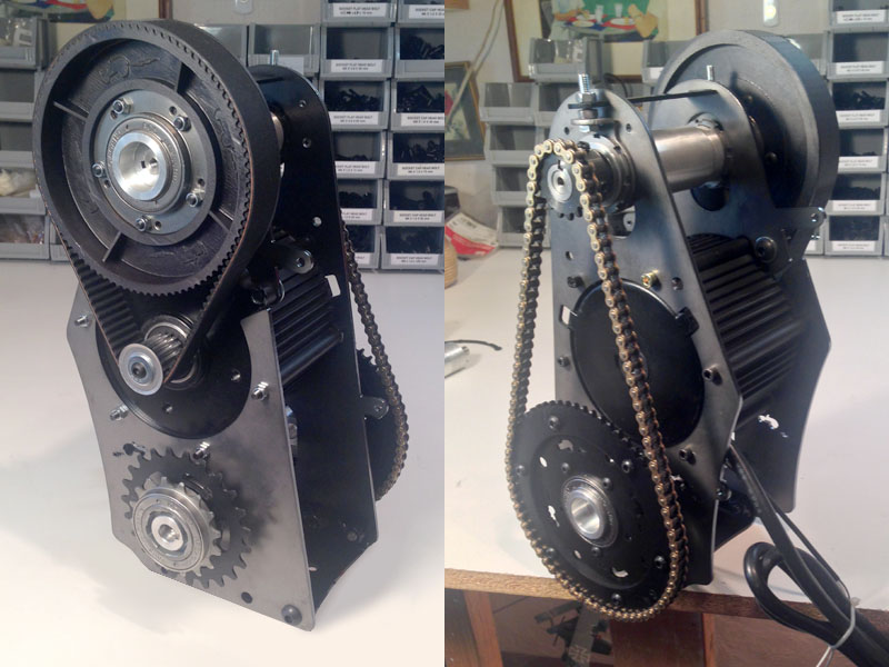
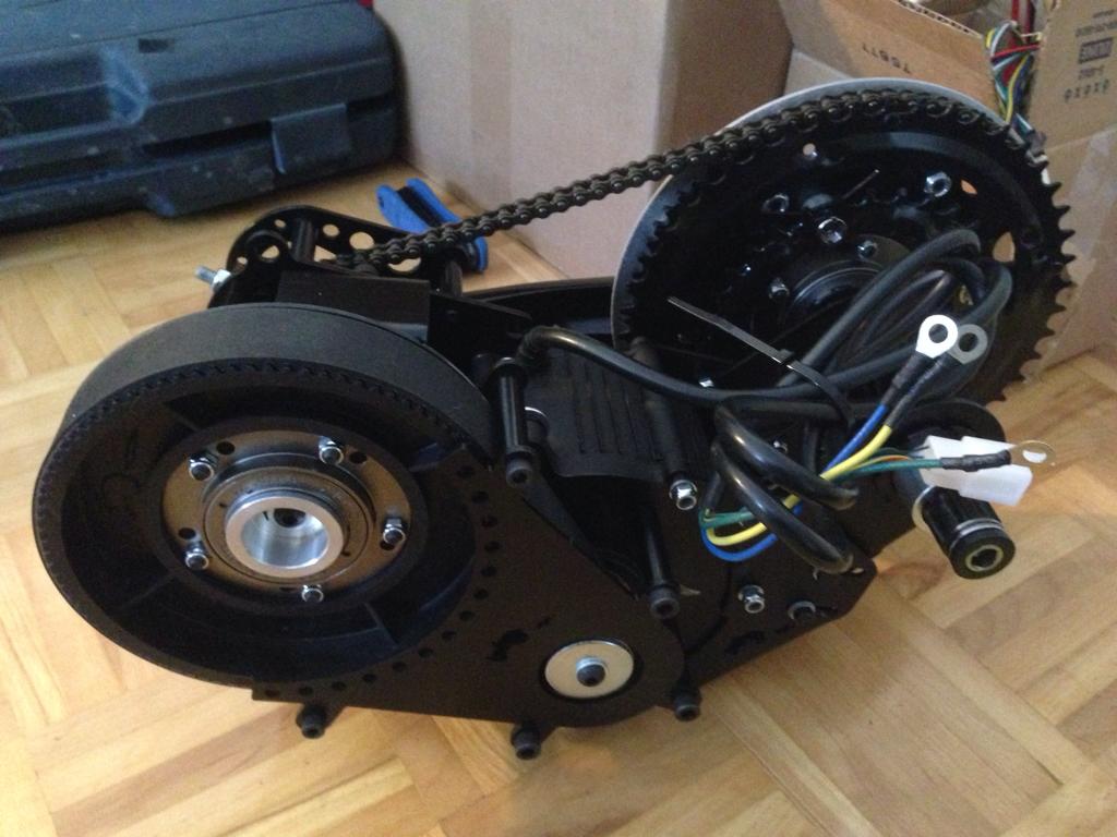
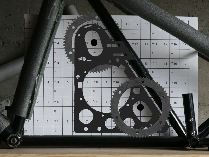
I'm writing today about your jackshaft option in the post I quoted from you. I was wondering if the configuration could be changed to a more triangular shape,
instead of inline in your post photos....
. O .
O . O
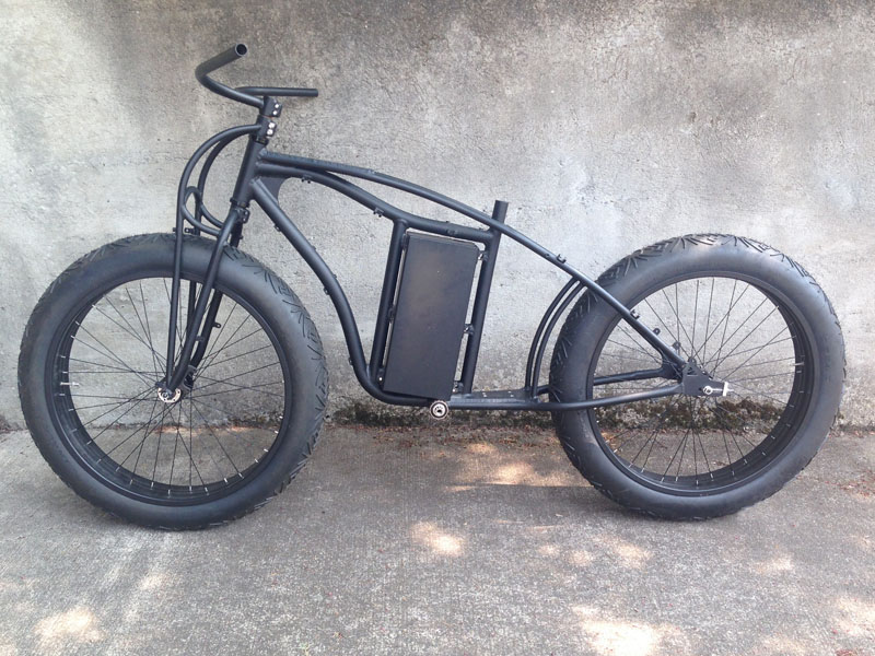
Lately, I've been playing with Fat Bike designs with custom frames that are stretched and slightly more low slung. I would like to incorporate a Big Block set up with a jackshaft into my creation, but as I see it, I would need this triangulated configuration to fit it as close to the rear wheel and behind the BB. (height is an issue)
I appreciate your time, sir, and any feedback would be greatly appreciated.

P.S.- So as not to derail this thread a piss off the OP, any questions about my gas bikes should be pm'ed to me.

Thanks!

BrettMavriK

""Whether you think you can or you can't,
eaither way, you are right." - Henry Ford
 
LightningRods said:
My standard mid drive is designed to deliver a 93 rpm pedaling cadence at 48V. How fast you go depends on your bike's final gearing and wheel diameter. If you get a 29er and put a 48T front drive chainring on the bike you will probably hit your speed target.

If you don't have a bike picked out yet take a look at the LunaCycle. My new mid bike drive for the Luna will have a pedaling cadence of 80 rpm @ 55 km/hr. It's able to do this because it has two stages of overdrive for the pedal power.

The two speed geared cranksets won't work with my regular mid drive kits because the motor needs to be able to drive through the BB chainwheels. It would work on the Luna drive except that bike has a 100mm wide BB and the Patterson type cranks are 68mm.

So thats means that the cadence is always 93 rpm no Mather the speed?
( yea im a rookie and im probably asking the dumbest question questions possible)
 
Brett, your gas bikes looks sweet! That black one is killer!!

Did you see the image of the original kit? It is more triangular than the newer inline kit.
2X8mnrP.jpg

You might even be able to alter the position of the bracket mounting to make it even more triangular...not sure if you'd need to change belts or not.
Mike is great assistance. You could forward him a pic of the actual bike you're interested in and he'd be able to let you know.
 
Here's the layout for my new mid bike drive for the Surly Big Dummy cargo bike. This drive does have a more triangular layout than the Luna drive. I agree, if you have the horizontal space to spread out and get comfortable, a triangle does make the drive more compact.

BigDummyLayout.jpg


The laser cut brackets for the Big Dummy drive, the Qulbix mid drive and the Luna drive are supposed to be ready for pickup today. :D
 
So thats means that the cadence is always 93 rpm no Matter the speed?

Andytheswede, the motor and reduction are coupled to the bottom-bracket (pedal axle). If you are using 48V, and the throttle is topped out, the motor will attain a certain RPM, and the BB will be spinning at 93-RPM's.

At that point, the chain goes back to the wheel, and the wheel diameter along with the number of gear-teeth on the sprockets are all controlled and chosen by the builder. I recommend using the largest diameter sprockets on the wheel that will fit, so as to engage the maximum number of chain-links into the gear-teeth.

If you raise the voltage of the system, the motor will run up to a higher RPM, and the BB will be spinning much faster than you can pedal, but...at high power and top-speed, most builders focus more on the watching the path, than pedaling along.

BrettMavrik, I really like the "soft-tail" shock linkage with the horizontal shock absorber (on the black bike). If I was making a street E-bike, that is what I would use, to free up frame triangle space. I have seen them on motorcycles, and that is definoitely the optimum way to go.
 
LightningRods said:
Here's the layout for my new mid bike drive for the Surly Big Dummy cargo bike. This drive does have a more triangular layout than the Luna drive. I agree, if you have the horizontal space to spread out and get comfortable, a triangle does make the drive more compact.

BigDummyLayout.jpg


The laser cut brackets for the Big Dummy drive, the Qulbix mid drive and the Luna drive are supposed to be ready for pickup today. :D

It's really cool to see how it will mount in the Dummy. I'm a bit late to the party, so forgive me if my questions have been covered. When the motor is not powered what is the perception of pedal drag? What is the chainline of this system, and is it adjustable independently of the crank chainline?
 
LightningRods said:
Here's the layout for my new mid bike drive for the Surly Big Dummy cargo bike. This drive does have a more triangular layout than the Luna drive. I agree, if you have the horizontal space to spread out and get comfortable, a triangle does make the drive more compact.

BigDummyLayout.jpg


The laser cut brackets for the Big Dummy drive, the Qulbix mid drive and the Luna drive are supposed to be ready for pickup today. :D

That's awesome, Mike!
That triangle set up is still more inline, albeit slanted from vertical however. What I am proposing is a near equilateral triangle set up, whereby the motor is on top, the belt drive is forward on the bottom, and the jackshaft is aft on the bottom. The jackshaft for me is the key point. Much better strength, reduction options, etc.
. O .
O . O
If it can be done, this would be ultra compact for streamlined design. This equilateral proposal would lend itself to even more custom designs like low slung trikes, etc. Also, since the jackshaft makes it an independent unit from BB's, it lends itself to more versatility.
The frames I have in mind would be completely custom designs by me. I'm thinking along the lines of a stretched Fat Bike, with a rigid rear end and possibly a suspension fork in the front. I've read where a Big Block motor and a derailleur is not a good option for multi-speeds (important to me), so a Rohloff would be the only option for strength. I would like the bike to be agile, fortified, and have a good, stable, and comfortable ride. Along with Function is Form...and I am HUGE on Form... :mrgreen:

It's gotta have Style, or I won't do it.

BrettMavriK
 
jtrops said:
It's really cool to see how it will mount in the Dummy. I'm a bit late to the party, so forgive me if my questions have been covered. When the motor is not powered what is the perception of pedal drag? What is the chainline of this system, and is it adjustable independently of the crank chainline?

The pedal chainline is joined to the final driveline at the lower jackshaft on the right side. If you want to pedal without the motor you are turning the jackshaft in it's bearings. The freewheel disconnecting the pedals from the motor is on the left side of the lower jackshaft. Drag should be very light when pedaling.

If you look at the upper mount for the motor bracket you can see that it's slotted for forward and aft movement. The two lower mounts are split blocks that can slide on the oval frame tube. There is 1" of fore and aft movement. On bikes with a derailleur this slide can be used to tension the pedal chainline. On bikes with a Rohloff or other IGH you will need an idler tensioner on either the pedal or final chainline. I'm working on a torque sensor for the pedal chain that will also double as an idler adjuster.
 
Thanks for the speedy reply. And you answered another wuestion that's been on my mind, chain tension. I'm currently using a Nuvinci N171, and as you probavly know the Dummy has vertical dropouts, so i have rigged an idler pulley that works pretty well, but it will have to change when I add the motor to the drivetrain. So,needless to say the torque sensor will be doubly helpful in my case.

It looks like your system has the flexibility to electrify my bike.

LightningRods said:
jtrops said:
It's really cool to see how it will mount in the Dummy. I'm a bit late to the party, so forgive me if my questions have been covered. When the motor is not powered what is the perception of pedal drag? What is the chainline of this system, and is it adjustable independently of the crank chainline?

The pedal chainline is joined to the final driveline at the lower jackshaft on the right side. If you want to pedal without the motor you are turning the jackshaft in it's bearings. The freewheel disconnecting the pedals from the motor is on the left side of the lower jackshaft. Drag should be very light when pedaling.

If you look at the upper mount for the motor bracket you can see that it's slotted for forward and aft movement. The two lower mounts are split blocks that can slide on the oval frame tube. There is 1" of fore and aft movement. On bikes with a derailleur this slide can be used to tension the pedal chainline. On bikes with a Rohloff or other IGH you will need an idler tensioner on either the pedal or final chainline. I'm working on a torque sensor for the pedal chain that will also double as an idler adjuster.
 
But doesnt that also mean, that for a guy like me who needs to do 30 mph for longer durations, and who wants to pedal along on top of that to get exercise, that I would be better served by a front or rear hub motor because it lets me set whatever pedal cadence I want while still doing 30 mph?

( can you tell I really want to buy Mikes kit? :-D)

Btw this forum should have a thread specific donate function so idiots like me could donate some money for taking up everybodys time with stupid questions.
 
Back
Top