LightningRods said:It would make the part more labor intensive and more expensive, but it would be nice to have welded captive nuts on the inside of the adjuster bracket for the side bolts to thread into. Fiddling with loose nuts up inside of the lower sheets would be extremely frustrating.

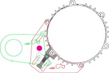
Mike, I was thinking about how to simplify the design so that it was more rigid AND less "fiddly". What if the lower sheet pivoted around a riveted axle, rather than slid. In the illustration, the pink circle would be a riveted axis of rotation. The motor would rotate around this and your single pusher bolt would provide the tension for the 2ndary chain. The advantage of this design (might) be that it would be easier to assemble and would not skew to the side due to the force of the chain. NOTE: the actual location of the rivet and the pusher bolt are not meant to be accurate in the picture. In fact, you'd probably want 2 pusher bolts, one above and one below the axis of rotation.
On the upper sheet, you could employ a similar idea. Pin one of the 2 jackshaft bolts in place so as to lock it perpendicular to the sheets. The second one would slide in an arc to provide tensioning. Also, since the size of the belt is known in advance, the range of adjustment does not need to be so great. Only enough to get the belt on and off.
Just an (untested) idea! It's easy for me to be "armchair designer"... I don't mean to imply that any of these ideas are better than what you've accomplished with actual metal.


