
The pulley was stuck i'm guessing the key on that shaft bit into that aluminum adapter i would need a "puller" to remove it something like this (http://www.apexinds.com/hardware/Pullers_2_Jaw-3_Jaw-Slide_Hammer-Posi-Lock-Bar.html) I didn't have one and i figured i could weld it without any issues so i left the pulley on. After i sanded and painted everything and it is almost unnoticeable that i scorched the pulley.
You are using an out of date browser. It may not display this or other websites correctly.
You should upgrade or use an alternative browser.
You should upgrade or use an alternative browser.
LightningRods mid drive kit
- Thread starter spinningmagnets
- Start date
Yeah i wouldn't pull on the plastic I would have grabbed the arms on to the freewheel. If i was having to remove the pulley often i would tap the large ID of that aluminum hub and machine a a screw with a pin that pushes on the shaft. kind of like a crank arm removal tool.
PaulD
1 kW
LightningRods
1 MW
Again, you're going to need an adjustable upper mount for this alternator style secondary adjuster to work properly. Rotating the entire assembly back at the BB undoes most of the adjustment created by the curved slide. With some fore/aft adjustment in the upper mount it could work great.
why plastic?
i'm sure everyone here but me knows the answer, but i was wondering why belt pulley is from plastic and not from the same material as the motor shaft.
also interested to know if anyone experienced belt slips during high loads ( for example full throttle on high gears ).
at this point i'd like to point out that even though the kit is currently not-operational (your'e still not getting it ganot") ) , it's been a interesting learning experience, to see how powers and stress effect materials in real life. i only wish i knew more to help (it's not like i can order a "for morons" book on amazon, hell i never even graduated high school).
) , it's been a interesting learning experience, to see how powers and stress effect materials in real life. i only wish i knew more to help (it's not like i can order a "for morons" book on amazon, hell i never even graduated high school).
another question, has anyone examined the teeth on the their driver sprocket after extensive use? to see if they got ..ah... thinner? i know the reason mine went AWOL l but i'm talking about when chain IS aligned correctly. i'm thinking if should just order another 12T sprocket, or have one made.
i'm sure everyone here but me knows the answer, but i was wondering why belt pulley is from plastic and not from the same material as the motor shaft.
also interested to know if anyone experienced belt slips during high loads ( for example full throttle on high gears ).
at this point i'd like to point out that even though the kit is currently not-operational (your'e still not getting it ganot
) , it's been a interesting learning experience, to see how powers and stress effect materials in real life. i only wish i knew more to help (it's not like i can order a "for morons" book on amazon, hell i never even graduated high school). another question, has anyone examined the teeth on the their driver sprocket after extensive use? to see if they got ..ah... thinner? i know the reason mine went AWOL l but i'm talking about when chain IS aligned correctly. i'm thinking if should just order another 12T sprocket, or have one made.
LightningRods
1 MW
"Go away kid, ya bother me."

notger
100 W
- Joined
- Mar 14, 2013
- Messages
- 279
Hi,
Cause we were talking about motors in the last time.
I added two seperate Thermistors for my kellycontroller to cut back current in case an for my ET-elogger to know what's actually going on in there.
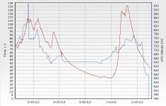
I Just made two rides in the last two days and measured a peak of around 130 °celsius on an intense up and downhill ride.
I was touching the Motor several Times while the ride to test how hot it would get, But the outside case was just cosy warm while it had boiling 130° inside. So touching the Motor is not a way to tell how hot the windings get
And i counsciously did support a lot on the uphill parts, cause workout is fun and i want to treat the motor with care.
I had peaks of 48Amps at 36Volts and sure Amps are related to the rising heat.
But really neat is the relation Motor Heat to Altitude, and how fast the Motor cools down again
I add the charts (red is temperature, blue Alt, they are not complete but cover the hardest part of the ride)
??? What Maximum temperature would you allow the Motor to get before the controller should cut back current ???
Cause we were talking about motors in the last time.
I added two seperate Thermistors for my kellycontroller to cut back current in case an for my ET-elogger to know what's actually going on in there.
I Just made two rides in the last two days and measured a peak of around 130 °celsius on an intense up and downhill ride.
I was touching the Motor several Times while the ride to test how hot it would get, But the outside case was just cosy warm while it had boiling 130° inside. So touching the Motor is not a way to tell how hot the windings get
And i counsciously did support a lot on the uphill parts, cause workout is fun and i want to treat the motor with care.
I had peaks of 48Amps at 36Volts and sure Amps are related to the rising heat.
But really neat is the relation Motor Heat to Altitude, and how fast the Motor cools down again
I add the charts (red is temperature, blue Alt, they are not complete but cover the hardest part of the ride)
??? What Maximum temperature would you allow the Motor to get before the controller should cut back current ???
Attachments

izeman
1 GW
i don't see any real problem with those temp. you didn't mention where exactly you installed the probes. some install them under a winding, some where the winding is connected to the phase wires, some glue them to the stator metal itself. temperatures will show the same values sooner or later. directly at the windings the values obviously will jump the most.
EDIT: sorry. it could be you have the sensors which LR installed, right? they are located nicely.
the CA has some temp limiting feature for controllers that don't have this feature included in it's firmware itself (like the eg the kellys). the kelly sets this temp to 125°c max for the controller. and the CA starts ramping down the amps at 90°C and will go to zero at 130°C if i remember correctly. you did just reach 130°C w/o limiting, so it looks ok for me.
notger
100 W
- Joined
- Mar 14, 2013
- Messages
- 279
Hi,
No i do not use the LR-Motor, didn't even know that there is a thermistor built in by default.
I use the "original GNG" and i tied the thermistor with a cable trap directly on the windings.
So i think i get the full load of themperature shown.
Where do LR-Motors have the thermistor located?
130°C seems alot to me cause of the Magnets.
RC-freaks told me they do not want to get their Brushless Motors warmer than 80°C to Keep the magnetism as long as possible.But sure it might not get 130°C on the Magnets if the thermistor shows it directly on the windings.
I wanted to know more about the inside temperature cause last time i opened the Motor it smelled quite toasted inside.
Also one Hall sensor was defect wich mighthave been because of too high temp.
I changed all three Halls now and put some High quality an temp Halls inside, and teh hold very good until now.
Next Time I open the Motor I Might add a thermistor for a Future CA wich kind of thermistor does the CA Need?
greets
Gernot
spinningmagnets
100 TW
"Temp sensor that's too cool not to share"
http://endless-sphere.com/forums/viewtopic.php?f=1&t=25502&start=50#p794933
A very common temp limit at the stator core is 93C / 200F. It is desirable to keep the temps lower than that, though. If you have the amp-limiting ability of a Cycle analyst, you might consider to cut the amps in half around 60C / 140F for a long component life.
http://endless-sphere.com/forums/viewtopic.php?f=1&t=25502&start=50#p794933
Any temperature sensor with a linear or approximately linear output can work in linear mode, and a 10K NTC thermistor with a 3900-4000 beta constant will work fine for the thermistor mode
A very common temp limit at the stator core is 93C / 200F. It is desirable to keep the temps lower than that, though. If you have the amp-limiting ability of a Cycle analyst, you might consider to cut the amps in half around 60C / 140F for a long component life.
notger
100 W
- Joined
- Mar 14, 2013
- Messages
- 279
Ok, just according to what i saw now i might consider mounting the thermistor not right on the windings and rather some mm beside them, to have some smoother measurements belonging the temp-peaks.
On the other side now i really see what's going on, on the hottest part of the motor ->the winding
I read some people drill holes in the stator and put the therm. in there, my impression is, that this would just measure a cooled-by-the-staror-mass-value and not the real heat that the windings have or radiate at that moment.
What heat shorttime peaks would you think would the windings of the gng motor take and what coninuous temp would be healthy for the magnets (or does anyone have concerns about the magnets)
greets
Anit
LightningRods
1 MW
Here are a couple of articles I liked on motor operating temperatures:
http://www.leeson.com/TechnicalInformation/hottopic.html
http://www.coolmagnetman.com/magstren.htm
I put my thermistor right on the surface of the core motor case, right between the windings and the outer case. I bond it to the surface with JB Weld. It seems to work. The one thing that Emaayan has not managed to do is burn up the motor (knock on wood).
DON'T SAY THAT! DAMMIT MAN, havn't you heard of jynxing someone? ? especially with my blundering history?? :lol:
yea the motor insides are ok, even when i set it to 50 amps (relax, like i said it's peak only ,for a less of 2-3 seconds) the motor always got around 60 degrees even after 45 minute ride.
i also switched to 4 mm bullets (to match my bmc, and because the 5 just ... looked ... so ... big) and that seems to be working finde as well. knock on wood, sacrificing small resistors to the ebike heavens.. etc... so say we all... so if L-R is preaching to use 2000 watts for continuous usage i think he can stick with 4mm.
i did manage to borrow a small insert in the allen housing used to support the adjusting screw of the lower sheets., but that's my fault before anyone gets any ideas. and i'm not worried about it ether. the little trick i did with the extended plastic part i placed to prevent the lower sheets from twisting seems to be working, you can even see the the part is leaning like teeter-toter as the result from motor force, but still preventing the twist. i didn't want to do two parts like L-R did because it's more convenient for me to reach for one. so i'm less stressed now about the lowers.
one thing i didn't get though, if the upper sheets are gonna get thicker, wouldn't the right one stick out more from the motor? (unlike the left one which can be thicker because it's installed inwards.
and won't it being thicker cause problems with the chain guard sticking out more towards the crank arm?
someone told me that the sheets could be used from something he called spring nirosta, now i KNOW this is not the english term,maybe you call it carbon steel, but that's how it put it in hebrew, from what i understand it's a metal that has undergone thermic treatment to prevent bends and deformations.
LightningRods
1 MW
12 gauge steel is .1046" thick. 10 gauge steel is .1345" thick. That's a difference of .029" or 0.74mm. So you can either suffer the anguish of having your sprocket guard 3/4 of a millimeter closer to your crank arm or you can file that tiny amount off of the tube spacers.
Most people on E-S know this but I'm just going to mention that your typical electric motor is going to be happier producing 1500 watts by 50V 30A rather than 36V 42A. Most of the articles that I read on motor heat recommended reaching the desired horsepower output by raising voltage rather than amperage.
Most people on E-S know this but I'm just going to mention that your typical electric motor is going to be happier producing 1500 watts by 50V 30A rather than 36V 42A. Most of the articles that I read on motor heat recommended reaching the desired horsepower output by raising voltage rather than amperage.
spinningmagnets
100 TW
yea the motor insides are ok, even when I set it to 50 amps (relax, like I said it's peak only, for a less of 2-3 seconds) the motor always got around 60 degrees even after 45 minute ride
I also switched to 4 mm bullets (to match my bmc, and because the 5 just ... looked ... so ... big)
Emaayan, I say this with love...as a friend...experimenting to see where the limits are on a new product is fun, but...when I do that I don't blame anyone else but myself when I break something and then post the pics.
You recently posted pics of how your kits mounting bracket twisted and then the sprocket was quickly worn down by the chain grinding at an angle. With electric bikes using 48V X 50A = 2400W, 3 seconds is all it takes when you are doing something wrong. If the 4mm bullets work well for this, fine. But if there is a problem with them getting hot, one of the first suggestions will be to go to larger connectors.
You mentioned needing to accelerate in traffic to keep up with cars, but you also wanted the efficiency of being able to downshift the gears when you get to steep hills. You may need to eventually add a second motor, perhaps a cheap BPM geared hub. The BPM is no hot rod, but if you put 1500W through the LR kit and 1500W through a BPM at the same time, the combined 3000W should provide the flat street acceleration you desire.
If your V1 brackets are twisting at 50A, brace the brackets in some way, and limit the kit to a lower amp-level until your get the kit sorted out for your application.
LightningRods
1 MW
Thank you Magnets. It takes a village to raise a child.
I was just walking around down in the shop and thought it might be fun to list the improvements that are coming very soon. Like next week.
New upper adjuster sheets with 10 gauge instead of 12 gauge steel and a pattern with fewer holes and extra metal for more strength. The right sheet incorporates a lug for mounting an optional torque brace if needed.
A new bolt in front brace for the upper sheets that creates a front box section and more rigidity to resist torque twist.
A new rear frame hanger that has twice as much contact area with the frame and provisions for two hose clamps instead of one.
Double lower adjuster bolts on all bracket widths.
Class 8.8 metric hex bolts for the slide adjusters.
Nord-Lock locking washers for the slide adjusters.
A new pattern and mold for the large driven pulley to dramatically improve the surface finish.
There is a lot more coming but I'm going to use up my existing inventory before announcing more upgrades. This kit will never stop improving.
I am also in the planning stages for a completely new mid bike mid drive for cargo bikes and other large bikes that have room between the BB and rear wheel to mount a mid drive. Two customer bikes are on their way to my shop right now so this is going to happen.
I've been using this down time waiting on the laser shop and our resident 3D printer to make a lot of the peripheral parts that will attach to the new main components. My shelves are breaking from the weight of all of the parts on them. I plan to start shipping kits as fast as possible.
Deanwvu
100 W
LightningRods said:I am also in the planning stages for a completely new mid bike mid drive for cargo bikes and other large bikes that have room between the BB and rear wheel to mount a mid drive. Two customer bikes are on their way to my shop right now so this is going to happen.
Crap crap crap... My intended install for the LR kit I ordered is for a cargo bike--a Surly Big Dummy.
Can you tell us some more details about this cargo bike model you are developing? Do you intend to mount it in the "extra" triangle of the frame between the BB and the rear wheel? What advantages would it have over your current model (the one I ordered)? One that I can think of is that I would be able to use the THUN torque sensing BB, as the BB assembly and crank area would be standard, correct?
LightningRods
1 MW
One of the two bikes I'm working with is a Surly Big Dummy. Yes the new mid drive will be located between the BB and rear wheel. Power from the motor does not go to the BB. The BB works as normal and connects to a jackshaft on the drive where it's combined with motor power. There are many advantages to doing it this way. One of which is that you can keep your stock crankset or go to a Thun or whatever you want. Not needing a freewheel in the BB opens up a bunch of options. All you need is the room to do it this way which most bikes (and virtually all full suspension bikes) don't have.
You can also use a more typical through the BB mid drive on the Big Dummy. This is really a matter of how big a hurry you're in. Since you've already been waiting for the original front of bike kit you're already in line for the mid bike kit.
You can also use a more typical through the BB mid drive on the Big Dummy. This is really a matter of how big a hurry you're in. Since you've already been waiting for the original front of bike kit you're already in line for the mid bike kit.
spinningmagnets
100 TW
Crap crap crap... My intended install for the LR kit I ordered is for a cargo bike--a Surly Big Dummy
1) Buy a used full-sus DH mountain bike
2) add the standard LR kit you ordered
3) sell
4) profit.
LightningRods
1 MW

Deanwvu
100 W
LightningRods said:One of the two bikes I'm working with is a Surly Big Dummy. Yes the new mid drive will be located between the BB and rear wheel. Power from the motor does not go to the BB. The BB works as normal and connects to a jackshaft on the drive where it's combined with motor power. There are many advantages to doing it this way. One of which is that you can keep your stock crankset or go to a Thun or whatever you want. Not needing a freewheel in the BB opens up a bunch of options. All you need is the room to do it this way which most bikes (and virtually all full suspension bikes) don't have.
You can also use a more typical through the BB mid drive on the Big Dummy. This is really a matter of how big a hurry you're in. Since you've already been waiting for the original front of bike kit you're already in line for the mid bike kit.
So, this would make it different from the right hand stokemonkey then, correct? Based on this picture, it looks like the right-hand stokemonkey does require a freewheel on the right side, as this bike still uses one large chain:

Does your design use two separate chains (one from crank to motor, and the second from motor to wheel)?? Does this put the freewheel in the motor assembly then?
Deanwvu
100 W
Also, what motor are you going to use for the cargo bike LR kit?
LightningRods
1 MW
If I remember my Stoke Monkey lore correctly you have to pedal along with the beast. I don't think that BB has a freewheel in it but rather is a front internally geared setup. My drive will have a chain from BB to jackshaft and another from jackshaft to rear wheel.
Both of my freewheels will be in the jackshaft. I plan to use both the small block and big block motors. The big block is a natural for cargo bike duty.
Both of my freewheels will be in the jackshaft. I plan to use both the small block and big block motors. The big block is a natural for cargo bike duty.
Deanwvu
100 W
LightningRods said:If I remember my Stoke Monkey lore correctly you have to pedal along with the beast. I don't think that BB has a freewheel in it but rather is a front internally geared setup. My drive will have a chain from BB to jackshaft and another from jackshaft to rear wheel.
Both of my freewheels will be in the jackshaft. I plan to use both the small block and big block motors. The big block is a natural for cargo bike duty.
The original Stokemonkey was a left-hand drive, and it did require that the rider pedal with the motor at all times. The picture above is of the right hand stokemonkey (the newer one), and that front crank in the above photo is a Grin cycles product that incorporates a 2 speed front crank with a freewheel. I think it may even have a torque sensor built in.
This photo is the original (left side drive) stokemonkey:

Similar threads
- Replies
- 5
- Views
- 1,910
- Replies
- 4
- Views
- 1,222
- Replies
- 6
- Views
- 639
- Replies
- 3
- Views
- 1,927
- Replies
- 25
- Views
- 6,532