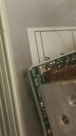
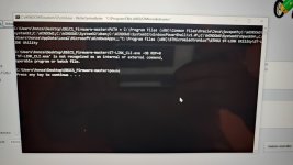
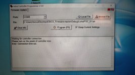
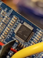
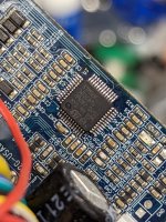
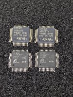
I was able to replace the clone STM32F103 with a genuine one and flash it with open source firmware. I had to lower the SWD frequency to allow flashing with longer wires.
Some observations about LSW12G-USAMK-F
Raw temperature sensor data is on PB0 - adcData[5]
Analog temperature sensor pin is pulled up to 3.3v using 3000ohm resistor
Digital SS1 pin is pulled up to 3.3v using 9300ohm resistor (or close to it according to my measurements)
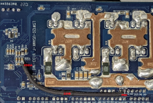
Below is the picture of traces below the MCU if anyone needs to follow vias.
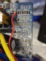
A good point to connect additional pull-up resistor is below, it is at 3.3v
(edit)
Updated 3.3v pull-up picture with correct VDDA location
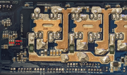
Connecting SS1 to TEMP_SENSOR (PB0) to 220ohm resistor with pull-up to this point gets ADC close to 200ohm of total pull-up across 2 joined pins, with acceptable range to drive both the digital and analog pins together.
Some observations about LSW12G-USAMK-F
Raw temperature sensor data is on PB0 - adcData[5]
Analog temperature sensor pin is pulled up to 3.3v using 3000ohm resistor
Digital SS1 pin is pulled up to 3.3v using 9300ohm resistor (or close to it according to my measurements)
Below is the picture of traces below the MCU if anyone needs to follow vias.


A good point to connect additional pull-up resistor is below, it is at 3.3v
(edit)
Updated 3.3v pull-up picture with correct VDDA location

Connecting SS1 to TEMP_SENSOR (PB0) to 220ohm resistor with pull-up to this point gets ADC close to 200ohm of total pull-up across 2 joined pins, with acceptable range to drive both the digital and analog pins together.


