Meanwell NES Schematic..almost complete

Shawn asked me to explain.

The mod was based off of the "SP" mod of the same version. Based on the schematic, thanks "NeilP", I was able to find the similar voltage divider. Off of Q1 and Q2 R1k and R36K make the voltage divider to the Isense pin of the PWM module. Unfortunately they have designed the circuit so that the R2 is a 36k ohm surface mount resistor, so this makes copying the mod for the "SP" not possible since it requires installing a potentiometer at or in parallel with "R2". IMO it is ideal to adjust R2 since you do not run into the problem of being able to over current the power supply by accident. In order to prevent this Ive found that you can include a series resistor with the pot in order to set a maximum current limit and still be able to trim to 0A. So in this case I've had to mod "R1" of the voltage divider to increase the value instead of decrease it. Also this is an easy to access 1K ohm resistor; marked as R55 on a genuine meanwell board(see pic).
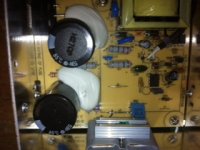
photo(1).JPG

Just to be clear you replace R55 with a pot greater than 25k ohm, include a resistor of at least 15kohm to create a max. current limit if you are worried about over current; since we have modded "R1" and not "R2"
 
Ok thanks.

i do not have a NES or SP here now, and probably am not looking at getting one again at the moment, as I have no need at the moment.

I know I am not going to get any time at the moment to look at this, as I have no need to, and to be honest, it is of no need to me at the moment, but for the sake of completeness, any chance you could produce a sketch or schematic of the mod..again , not for me, but for anyone in the future that may want to also carry out this mod.

I used PCB Express for the schematic, and I could send you the file for you to add the mod to if you had the time

Interested to see how this mod differs to how Cor did his mod

Cheers for the help in this,

Neil
 
I am not sure how the other mod is intended to work...I wasn't willing to try it based on the discussion and posted results. Also I didnt quite understand it.

Modding the shunt is always a last resort IMO because it is too imprecise/unreliable.

This mod differs in that its a simple single resistor mod, you cant mess it up....tested and works from 0 - 9A at 50V and 100V. It is indicated on the schematic by the black box and the resistor has been relabeled as R55.View attachment NES 350-48 01 .bmp
 
Ah nice one ,. ,cheers, am sure that is going to be very much appreciated by many other members,..and only your second post too.

8)


VANDY said:
Modding the shunt is always a last resort IMO because it is too imprecise/unreliable.

TOTALLY AGREE, shunts mods..ugg. I know I can be fairly ham fisted in some things I do, but shunt mods leave me cold
 
There is a thread about this guy who blows up meanwell's like they are candy...search for "sp-320-48 meanwell mod" of something like that. No sense re-posting what has already been done. I believe the mod involves swapping "R33" with a 1k Ohm pot...haven't modded one since last year. This mod requires turning the pot to 0 Ohms, I believe, in order to limit current and is more intuitive....aka easier not to blow up when testing the limit.
 
VANDY said:
There is a thread about this guy who blows up meanwell's like they are candy...search for "sp-320-48 meanwell mod" of something like that. No sense re-posting what has already been done. I believe the mod involves swapping "R33" with a 1k Ohm pot...haven't modded one since last year. This mod requires turning the pot to 0 Ohms, I believe, in order to limit current and is more intuitive....aka easier not to blow up when testing the limit.

Right on Vandy!

Welcome to ES, and thank you for your help!
 
hahaha was that too obvious? I wasn't sure about the etiquette on ball busting... lol

I've been reading the forums for a few years, that's how I met the guys in Pickering. They finally convinced me to post, just to explain the charger mod, since it seemed that the solution was not posted yet. I use this power supply for testing motors, controllers, discharge circuits etc. Ive tried to take out 50A with the power supply current limit set at 8A, with no problems.

If anyone needs genuine meanwell with mod. let Steveo or I know...otherwise the mod is available for all eyes to see.
 
VANDY said:
I am not sure how the other mod is intended to work...I wasn't willing to try it based on the discussion and posted results. Also I didnt quite understand it.

Modding the shunt is always a last resort IMO because it is too imprecise/unreliable.

This mod differs in that its a simple single resistor mod, you cant mess it up....tested and works from 0 - 9A at 50V and 100V. It is indicated on the schematic by the black box and the resistor has been relabeled as R55.


Hey Vandy

Did you ever work out an exact figure for R55 to drop the current to a figure below max..say 6.5 to 7 amps? Have just ordered a new NES and was thinking to save the hassle of a pot, I might just fire in a single new resistor, knock out the 1K R55 and replace it with a ???

Cheers

Neil
 
OK, well a few findings and mods I have done to mine

I used a fixed resistor at R55, to bring the current down to a fixed amount...I would have to rip it apart again to check the value, but seem to think it was about 36kΩ gave me about 6.5 amps.

I also took a 12 volt feed off the regulator that feeds the fan, to power an external voltmeter.

I also bridged the Collector/Emitter of the transistor that switches the fan on/off..so the fan now runs constantly.

Also fitted an early version Fechter CC/CV board, wiring the board control output wire direct to the OVP point.

have uploaded two pictures here. the one that displays at 800 pixels. and also the full size image if you want to see it full size

Fan-and-12-volt-mod.gif

Fan-and-12-volt-mod-done-.gif
 

Attachments

  • Fan-and-12-volt-mod low quality.jpg
    Fan-and-12-volt-mod low quality.jpg
    492.1 KB · Views: 2,704
Thanks to everybody's help, not least NeilP who supplied the very clear photographs my first lipo's are now bulk charging :D

I replaced R55 with a 50k multi-turn potentiometer to control current, and performed the fan always on mod.

I have installed an arduino voltage / current monitor which will turn the charger off when the pack voltage reaches 49.8v (cell voltage of 4.15V if all cells are equal). Here is a photo of the Mean Well / Arduino hybrid about 30mins after I set the cells balanced to 3.8V to charge....

file.php

file.php


The grey box with the red light on it, located to the right of the fan, is a Solid State Relay which is used to allow the Arduino to shut down the charger.

Anyway, I couldn't have gotten this far without the help of NeilP and the other members which have taken their own time to post such useful information.

Please forgive the rat's nest of wires, my next part of the project is to tidy them up!

Thanks

John
 

Attachments

  • arduino voltage.jpg
    arduino voltage.jpg
    59.1 KB · Views: 2,637
  • arduino current.jpg
    arduino current.jpg
    61.3 KB · Views: 2,637
Nice work
just wondering if you could cause the arduino unit to feed into the OVP ( over volt protection ) point on the board, just off to one side near the meanwell green LED.

This is the point that Fechters CC/CV board taps in to. The CC/CV board pulls the voltage (up ? down?) and controls the current of the meanwell and acts as a system shut down too.

Would need to wait for someone that understands the exact mode of operation of the CC/Cv board to chip in, but if you could get the arduino unit to perform the same job, then that may give a more flexible control of the Meanwell.
 
NeilP said:
Hey Vandy

Did you ever work out an exact figure for R55 to drop the current to a figure below max..say 6.5 to 7 amps? Have just ordered a new NES and was thinking to save the hassle of a pot, I might just fire in a single new resistor, knock out the 1K R55 and replace it with a ???

Cheers

Neil

Hi Neil,

From my first few bulk charges it appears that the R55 mod works as a current limiter but not a constant current selector. I previously charged my pack cells from a slightly discharged voltage of around 3.9v to 4.15v and adjusted the R55 potentiometer to allow approximately 5.5amps of current. As the pack charged the current applied decreased, as I expected from reading other's experiences with Mean Wells. After a 10mile bike ride, last night I charged the pack's cells from around 3.8V - upon starting the charge I noted the current being delivered was around 7amps - a little too high for the charger to continuously ouput! I altered the resistance to further reduce the current being applied.

From further charge cycles, it appears that as the voltage of the battery pack reduces, the current which the Mean Well will supply increases for any given R55 value. Therefore a single R55 value will not provide a constant current during pack charging.

The simple solution is to fully deplete your pack, then attach the charger and set the desired maximum current via the R55 potentiometer. The problem with this simple solution is that as the current the Mean Well outputs drops away as your pack voltage increases - even though the charge is not nearing completion. The ideal solution (for me) would be to have a microcontroller variable resistor such as this to allow me to vary R55's value throughout the charge based on the pack voltage.

Cheers

John
 
Ah yes, I found this too. charge current really drops off ...so the search for the elusive current mod continues...or use a Fechter CC/CV board
 
FWIW - I've been running one of my NES-350-48's without any mods at all to charge a 12s pack (49.8v cut off). It show a peak current of 390 watts.

It's clocked nearly 150hrs of charge time so far. Maybe the NES's don't actually need a current limiting mod?
 
Lost track of thread...If you have a charging circuit on your BMS it might be possible to plug directly into a power supply without any current limiting modifications.

The value for R55 is determined by the individual pack, every pack is a little different and should be calibrated to the charger. Johnamon is on the right track on how to properly calibrate the meanwell as a charger...You need to understand that charging is done by creating a voltage difference....since we are using a constant voltage we are limited in how we can set the current without using a variable resistor..i.e. we must set it for the largest voltage difference that the charger will experience. That being said the batteries also affect the charge since the internal resistance changes with the level of charge. So if your pack starts to become over 80% charged it will be impossible to force current into the battery; the current will always drop off near the end of charge. A way around this is to over voltage the charger, creating a larger voltage difference between battery and charger...this is too risky IMO, even if you can charge faster, and can easily overcharge your pack! Do not over voltage your charger! I always set my chargers for 4.15V per cell; in case there are slightly out of balance cells this might save your them from overcharge.

Mean-well mods are really only bulk chargers....not intelligent charging at all. I use this as my main charger and then every so often, every 30-50 charges, I will do a maintenance charge on intelligent balance chargers to bring all cells to 4.2V for lipo. I am switching to a 60V charger that comes equipped with voltage and current pots already built in. So far no problems, I wont be able to put it through its paces until spring...it gets a little warmer than meanwell, but a simple moved temp. sensor fixes the problem.

IMO the best bulk charger would make use of variable voltage and constant current....the power supplies are excellent candidates for this. Just need microcontrolled variable resistors, as well as voltage and internal resistance monitors. Setting the current maximum of a given power supply for lowest voltage difference possible, for a certain set of cells, would allow for the fastest charge. Every set of cells would require a certain charging profile based on the change in internal resistance of the set of cells, not just the change in voltage.

Otherwise you just have to sit and wait for the extra 5 or 10 mins that you save by pumping the max. current into your batts for as long as possible.
 
Back
Top