Methods 100V 100A Programmable Regen Controller

Methods, you beat me to it. I just sat down to start getting all this stuff in one place and you've already begun! I saw Geoff's stuff, but it was missing some of the info for the fields.

Do you think it'd be worth taking some of the general descriptions from the PDF file in the tech.ref. forum and your own instructions to help flesh out some of the "How and Why" each fields value are chosen.

Here's the rest of the info for the other fields. This info is taken from this thread. http://endless-sphere.com/forums/viewtopic.php?f=2&t=12255&p=183518&hilit=keywin+lab#p183518
stator said:
Most of it is already documented in this thread in the Technical Reference area:

http://endless-sphere.com/forums/viewtopic.php?f=16&t=7531

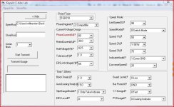
There are some new setting available in this version of the software. Here is the description of those new settings:

Guard Level: The controller has a anti-theft feature which is activated through the TB pin. This sets the polarity of that signal. The default should be 0:Low. In this mode, a low signal on the TB pin will lock the motor from turning. Presumably, this signal would come from a external alarm system. In the 1:High setting, a high signal on TB will lock the motor. In order to use the High mode, you must remove the 51K ohm resistor at location R75.

Bar Protect: This is a throttle fault protection feature. When active (1:Yes), it will shut off the motor if the throttle input is shorted to +5V. Normally WOT is around 4V, so if the wires short, or the hall sensor shorts, it should go close to 5V.

1:1 Design: This is for pedal assist sensor operation. The options are 0:Fast and 1:Slow, but another document says 0:False and 1:True.

P3 Design: This sets the function of the P3 LED output. When set to 0, the P3 output is active when in cruise control mode. When set to 1, the P3 output will also blink a trouble code when a fault is detected. The P3 output (along with the speed LED signals P1 and P2) can be active high or active low depending on the setting of "Indicate Mode". For active low, set it to 0:Comm VCC (all LEDs share a common + voltage). For active high, set it to 1:Comm GND (all LEDs share a common ground).

--Bill
 

Attachments

  • Infineon cheat sheet.jpg
    Infineon cheat sheet.jpg
    105.5 KB · Views: 2,518
somewhere on E-S there is a pic of the parameter designer with the fields numbered and descriptions below. I saw it last night and I should book marked it, but can't find it now.

got this from a Knuckles post about the slipchargemode field, but the pics didn't make it:
http://endless-sphere.com/forums/viewtopic.php?f=2&t=8317&hilit=parameter+designer#p125981
The degree of regen is software set using the PC flash cable.

There are 3 settings ... EBS Level: 0, 1, and 2 (low medium and high).
I set the level to "2" by default (perfect setting for a 26" wheel).
Lower values (0 or 1) may be better for smaller diameter wheels.

EBS_Level.jpg
EBS_Level.jpg (13.98 KiB) Viewed 3136 times


When the eBrakes are applied the Direct Drive hub motor will slow down to a complete stop.
(Max regen voltage is capped at 60V but can be increased to higher values by altering the R12 resistor value.)

Slip_Current_Charge_Mode.jpg
Slip_Current_Charge_Mode.jpg (13.03 KiB) Viewed 3128 times


The Slip Current Charge Mode feature is either "ON or OFF" and allows regen from the throttle.
Throttling back when cruising will regen the Direct Drive hub motor and slow it down to about 15% of full speed.

The eBrake regen and the Throttle regen act independent of each other.
I set the Throttle regen to "OFF" by default (I like to coast freely when throttled back).
It is just a matter of personal preference.
I think between my couple of posts and yours there will at least be basic info for every field now.
 
methods said:
will_newton said:
I am thinking of using your DC30AC80_65ADC.asv as a template, but with voltage set for 17S lipo. I have a problem getting a 3.2 v/cell cutoff, which using your conversion info from page one should be 45v, but I can only choose 42.5v or 51.5v, nothing in between.

I would use the xlyte example then use the current settings from the above asv
That DC30A was set up for the older Infineons so I did not address all the settings.

As far as LVC goes... You really need to do cell level LVC - otherwise just set the LVC arbitrary higher than the actual LVC
The last few volts are pointless anyway.... I would not even take my pack into that zone.

-methods
You xlyte.asv and DC30A.asv hybrid suggestion is exactly what I did last night. I have Gary's LVC battery boards, so I do have cell level protection. I was just curous about setting the LVC on the ESC, I usually "self monitor" using the CA down to 3.6v a cell and call it a day, but was just looking at a hard cutoff voltage inside the ESC and noticed there were a range of numbers missing.

Methods, would you mind looking at my programming setup just to check behind me?? I'll take a screenshot and post it up in a few minutes, I have to go to my PC (on the Mac now).
 
Put it together and I will add it to the Technical Reference Area.

-methods
 
my setup for a 9c motor on 17S lipo with no regen and a 3-spd switch.

I chose 42.5 as the LVC cutoff, which according to Methods is about a 50v cutoff, which gives me a third level of protection at 2.9v. If I had chosen 51.5 (the next number available) I'd have a 3.6v cutoff, which is too high. Keep in mind, I have a CA to keep a general watch on the voltage and LVC modules set for 3.2vthat are mounted on my battery packs to track voltage at the cell level. I ride until about 3.6 v a cell or 80% DOD according to the CA and then recharge. But even that is rare, as I generally top off the charge as needed rather than letting it drain all the way down to even 3.6v/cell. It keeps the charging/balancing sessions shorter that way.
 

Attachments

  • Capture.JPG
    Capture.JPG
    58.9 KB · Views: 2,515
This is a direct link to the ESC programming instructions post that I used in my build thread. It assumes that you, like me, are a near idiot. Hopefully my struggle will help other folks get a leg up and start to understand how to use this equipment. Thanks to Methods and all the other E-S techies whose archived info help me get this together.

http://www.endless-sphere.com/forums/viewtopic.php?f=6&t=14432&p=219858#p219858

Methods, I'll try and put together something more formal for the tech.ref. forum and you can move it there.
-update-getting it together now, using a spot in my build thread as a placeholder while I work on it-a direct link to it will be forthcoming.
 
This is the direct link to the Keywin e-bike Lab Parameter Designer Information thread I spent most of today putting together. Feel free to add some comments and corrections, preferably over there. After some proofreading or additions, I hope this amalgamated info to make it to the Technical Reference Forum.
http://endless-sphere.com/forums/viewtopic.php?f=2&t=14807
 
Wow... I just glanced at it (crazy busy packing boxes) but that is amazing.
Definitely going in the Technical Reference area.

GOOD JOB!

A nice follow-on would be for someone to hex-edit the program to display better names.
Who wants to do it?

-methods
 
Thanks Methods. I used lots of your info, so thank you too!

I was just wondering what the fields were for and once I really started digging hard, I found lots of stuff. Basically the E-S community had put together nearly an entire manual, but it was EVERYWHERE. I suspect there are even more nuggets lurking somewhere.

I may not know much, but I can sure as hell use the search function. :D
 
will_newton said:
I may not know much, but I can sure as hell use the search function. :D

That is the most valuable tool anyone can have on a forum like this.
Dont need to be an EE - just need to know what you are looking for and how to find it.

When i catch up on my email I will move that post.

-methods
 
Will,

Great work on the Infineon Parameter Designer manual !!

If anyone wants to specify what default files to include with a full setup.exe I will build my existing multi designer installer to be idiot proof and make the software much simpler to handle... I can add a pause loop in the setup program to detect when the USB adapter is connected and confirm success before finishing setup.

At this point, the software instructions (across various windows versions) are enough to scare avg computer users away... it doesn't need to be so complicated for the end user.

-Mike
 
Methods,

In your accessories package, is the reverse button a simple switch ?

If so do you see any problem if I rewire it in series with the round red switch mounted on the controller?

I don't care much about the reverse feature, but it would be nice to have a "kill" switch on the handlebar.

file.php
 
Hmmmm... Yes and no....

There is some risk in that you will be hanging an 8' long 100V Antenna... Pay attention to system noise and more importantly - MAKE SURE YOU DONT PINCH THAT LINE - because if you do you will have a serious melt-down. That line is a direct shot to the battery.

The switch is probably not rated to 100V so it is possible that it will fatigue over time.

Would I try it? Sure :twisted: Why not.

-methods
 
El_Steak said:
Methods,

In your accessories package, is the reverse button a simple switch ?

If so do you see any problem if I rewire it in series with the round red switch mounted on the controller?

I don't care much about the reverse feature, but it would be nice to have a "kill" switch on the handlebar.
hi
if all you want is a kill switch then instead of running a pair of wires from the red switch why not use the brake line like a parking brake on a car, or connect the throttle output signal through the switch so the throttle information can be cut and the motor will stop.
There will be no " 8' long 100V Antenna " no chance of a 100v short burning a hole under your ass.
Geoff
 
Or you could use a relay the automotive type horn/headlight/universal relay and run low voltage to the trigger side and the high voltage would be switched. So where ever you run the switch has low voltage and you can keep the relay in a safe place with short wires on the hi voltage side. This is what relays were designed for other then it is usualy hi and low current they control!
 
I considered relays, but missed out on the Kilovac EV200 contactor deal @35$ :cry: .

So I decided to give the switch in series idea a try...

To help prevent penile electrocution I added a small fuse on the line in case I pinch/short the wire. The wire will also be protected in a braided sleeve when installed and some of it will run inside my TidalForce frame.

It works fine but I only tested it with my old Ping pack at 54V. I like the fact that both switches need to be ON for the bike to run. The controller switch will not be easily visible on the bike.

switch.jpg


Hey, am I the first one to "modify" one of Methods controller :?:
 
El_Steak said:
Hey, am I the first one to "modify" one of Methods controller :?:

Warranty VOID :mrgreen: :mrgreen: :mrgreen:

I will send you one of those expensive relays if you want.

Jokes aside - even though the board is conformal coated - PLEASE remember that you need to discharge the main caps before putting the board back into the case. The +5V line shorts to the +V line during that operation (as doc learned) and if the main caps are charged they will blow the board.

-methods

P.S> Put the fuse external where you can get to it :wink:
 
methods said:
P.S> Put the fuse external where you can get to it :wink:
Fuse?
 
methods said:
Warranty VOID :mrgreen: :mrgreen: :mrgreen:

Damn, I didn't even know there was one !

methods said:
PLEASE remember that you need to discharge the main caps before putting the board back into the case.

Can I trust that the caps are fully discharged when red LED on the controller goes out completely ?
 
El_Steak said:
methods said:
Warranty VOID :mrgreen: :mrgreen: :mrgreen:

Damn, I didn't even know there was one !

methods said:
PLEASE remember that you need to discharge the main caps before putting the board back into the case.

Can I trust that the caps are fully discharged when red LED on the controller goes out completely ?


You should throw something across them like a 50ohm resistor, then wait a little while, then twist the + and - lead together on the controller for the time you slide the board back into the case. This ensures no damage to the uController while sliding the board back into the case. :)
 
Back
Top