Micro Lebowski Controller - DIY 3kw

What about bolting them togeter by M3 or M4 screws? Guess this will intuce larger resistance?
Yeah that's what I was thinking I wanted M4 threaded copper but don't think it exists. just solder perhaps.

Could the bottom and middle PCB be merged in the next iteration?
I thought about this but wanted to keep the driver and phase sense circuits somewhat isolated from the FETs. as you say there really isn't much on the bottom PCB. just the FETs underneath

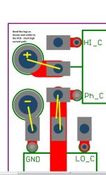
The connection from the vertical bus bars to the FETs is pretty short right?
HighCurrentPath.jpg

ohh. I just had a though. I could "slot" the PCB instead of round holes and connect 1mm think copper strip laminated together and insulated with kapton tape or something. That might be better I think.

That's it for now. of for a walk with my wife and son. :D :mrgreen:
Andy
 
Refer to the front page for the parts list $220 ish for parts... some parts (FETs and the current sensors) could be purchased cheaper from elsewhere, but they are all listed from a single source. feel free to search for alternative suppliers to save cost.... I have checked the PCB footprints

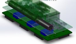
Here's a render including some Capacitors. I'm not sure about which caps to use, but these fit...

They are:
EPCOS - B32522C3474K - CAP, FILM, PET, 470NF, 250V, RAD
http://au.element14.com/epcos/b3252...nf-250v-rad/dp/1200748?Ntt=epcos+B32522c3474k

and

NICHICON - UHE2A121MPD - CAPACITOR ALUM ELEC 120UF, 100V, 20%, RA
http://au.element14.com/nichicon/uhe2a121mpd/capacitor-alum-elec-120uf-100v/dp/1899579?Ntt=1899579

And here's the picture
Lebowski_Caps.jpg

Andy
 
nice to read good news, i'll keep my fingers crossed that the it works.

3x 120uF sounds like very little to me. The 12-fet infineon controllers have four times of that. Is there a rule of thumb? Does it have to do with the minimal possible inductance of the motor?

Also why do you use a 250V rated film capacitor? Do you think a 100V one wont do the job (for long)?

Sorry for asking so many questions :oops:
 
To be honest I just found the same series capacitor that Lebowski used and then just picked the Biggest uF I could find that would fit

I could fit more capacitance by parallelling them I should be able to squeeze 3 more in there along side the first three but I will know for sure when I get everything

Andy
 
@ Alan B: these Caps come for $0.16 lol. Is this really up to cost?.. or more up to design? Thanks for giving direction, now i can read further about that topic!

@ Animalector: there is actually an impedance rating for your 120uF Caps: 0.2Ω @ 100khz, 20°C (standard ambient) and 0.84Ω @ -10°C (quite cold). Tracks to the FETs add up to this i guess.
 
I'm open to suggestion on what caps to put in there. Given the stacked layout a10mm diameter cap would be ideal 30mm long. As I mentioned earlier I could parallel two of these per phase.
 
When talking about DC link capacitors, you want high ripple current capability. Usually, with aluminium electrolytic capacitors, this comes with high capacitance values, but a controller really only needs very little capacitance compared to the amount the electrolytic types provide. The better choice would be film capacitors, they have much higher ripple current ratings, and are lower capacitance values, but comes at a much higher cost. So the economic way it to parallel electrolytic caps to increase their collective ripple current capability, but this also increases capacitance to a level where it does nothing for the controller, but it doesn't harm either (except for sparks when connecting the battery, use an anti-spark circuit to prevent this).

The smaller film capacitor is not for DC link, it's for another purpose, I don't fully understand this, but it has something to do with some spikes generated by the MOSFET switching.

With 80V target voltage, you want 100V or above capacitors. The 10mm diameter really limits the possible ripple current rating, I cannot easily find any with more than 1A ripple current, like this one:

http://www.digikey.com/product-detail/en/EKYB101ELL121MJ25S/565-4014-ND/4843824

1A don't seem like a lot to me but Lebowski can manage with a total of 1.5A from one cap in his controller. Why 1A does not seem much to me is because if you do the math, the ripple current is huge. What is the inductance of the target motor? 25µH? I don't know if that is a good guess, but with 80V battery voltage, 21kHz PWM and 25µH motor inductance, the RMS ripple current would be 27A! I'm sure this is only a theoretical number, otherwise most controllers would burn caps all the time. The math is from HighHopes, but I think it is a worst case ripple current, or it is the ripple current inside the controller, but since the current doesn't really stop flowing from the battery, the capacitor does not see all this ripple current, only the part the battery can't supply. That is just my personal theory :D
 
I don't think that it would make sense to save a cent or dollar when building the most advanced controller

I agree..

ok. how about this... the size is currently fixed by pcb design. I'll see what Caps I can physically cram in there. if this turns out to be insufficient, I'll modify the design or hang the big Caps out the side. no big deal. How will I know if it's not enough?

The question still remains... is what I have there insufficient / adequate? Irrespective of cost (since I was searching based on parameters other than cost.)

I'll have a read through Zombiess and High Hope's info about caps again, and this time try to absorb it.

Andy
 
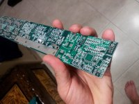
Well the GND plane is not shorted to the 5V plane, and it all of the GND pads I have tested have continuity, no shorts, build quality looks very good, very precise.

THere's a few minor issues. some of the interconnects between the Driver Board and the FET board haven't got a solder ring. because I used a large Via rather than a PAD. oversight on my part.

but it'll still be workable.

Time to order parts. I've just booked a Downhill biking holiday to New Zealand so that's consuming my available cash at the moment.

See how we go

Andy
 
ok I've priced up all the parts and found alternate suppliers for some of the more expensive IC's.

I can supply a complete kit all parts, PCB, IC's, caps, resistors, etc etc, PCB, NOT INCLUDING the lebowski brain for $200USD plus shipping. (order that from lebowski yourself)

This is a prototype, I've not built one (yet), but if people want a kit, a bulk electronics order is the way to go, I get good price breaks at >5 quantity for most stuff.

Anyone interested PM or post here in the next couple of days as I am going to place an order for parts to build up my first two boards.

Thanks
Andy
 
Just wanted to say I’m watching this with interest. A compact 6-FET FOC sounds perfect for my needs - modest power but sophisticated control. The Grin prototype looked excellent but pricey, besides which something like this is a fun and instructive project, with the potential for customization. Hopefully by the time you have this built and tested I’ll have acquired some SMD equipment and technique - I learned through-hole a long time ago and it’s time to update my skills. Good luck and keep us posted!
 
i thought the very same thing, and i really welcome andy's engagement. justin's controller would have been an instant buy, and too small for my needs. 3kW is a sweet spot for me. 6-fet is really small and with all the features and config to play with i'm sure it will be an excellent piece of hardware.
there's only ONE thing i hate about my bike: it's ALWAYS in a state of change. this is ok in winter time, but i hope to get it up and running (what i basically IS at the moment, but due to improvements it's not) by spring time.
 
Hopefully by the time you have this built and tested I’ll have acquired some SMD equipment and technique

Technique is a big part of it, but as for equipment, there's not much you need really. I've seen people try to use a hot plate and paste, but to be honest a good soldering iron with temperature control and a few different sized tips is all you need for SMD / SMT work... The only issues you face are with hidden pads on the bottom of IC's. it the legs are exposed it's not worries but as soon as you get a BGA / or something the only real alternative is an oven.

I got some solder paste and a stencil for some other PCB's I did in the past, but placing the components by hand on the paste was actually more difficult than tacking them with solder. and an iron. Plus there was the issue of 'unsoldered" paste balls causing shorts...

A microscope really goes a long way to SMT / SMD soldering quality. hmm I don't have one of those any more.. But that's why I chose 0805 components instead of 0603 :mrgreen: or 0402 :twisted:
 
Animalector said:
..But that's why I chose 0805 components instead of 0603 :mrgreen: or 0402 :twisted:
+1 for that decision. 0805 is WAY easier to solder. not that much because of the size, but also because of WEIGHT. those super small parts tend to stick to the soldering iron (if you take too little flux). the heavier 0805 tend to stay in place more easily.
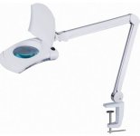
i also like a desk lamp with included magnifying glass.

Capture.JPG
 
I bought an Amscope stereo inspection microscope something like this:

http://www.ebay.com/itm/AmScope-SM-4B-80S-7X-45X-Zoom-Magnification-Circuit-Inspection-Stereo-Microscop-/140927277226

It is light years ahead of the head magnifiers or lamps with a lens as shown above. Seeing is everything.

The whole setup of microscope, IR board preheater, SMD hot air pencil and soldering pencil cost less than a cromotor and 24 FET controller, and it will easily handle fine pitch and those pesky ICs with solder pads in the middle. The pencil draws the smoke into a tube mounted on it, you don't want the smoke coating the microscope lenses. A front barlow lens on the microscope doubles the working distance so there is lots of room under the lenses for working on the board. I've built at least 50 small boards on it without any failures.
 
The stereo microscope puts your head in a much more upright position than other bench work, with the barlow lens it is way above the work.

The stereo feature allows the eyes to really see what is there, and you can tell if a spec of dust is conductive or not. The resolution is very high. The brain is very good at combining two images into one higher resolution visual image.

I haven't tried the monitor type camera system but I suspect the microscope is better from a resolution standpoint. But either should work.

I actually have a camera on my Amscope but the resolution and field of view are poor.
 
Back
Top