• Hello ES! We could use some help to get us past the finish line on building the new knowledgebase for the forum.
    Can you donate? Please see our fundraising page. Thank you!

MOD seated scooters up to 72V 5kW dual motor: VESC + modular DIY OpenSource electronics and software

In August 2024, I was riding far from home and the rear tire got flat!! I were using inner tubes with sealant so I asked at a home I found, for help, to try to fill the tire with air in the hope the sealant would fix the issue. But no, was not possible!! I had to ask a long car ride to carry me and my Fiido Q1S.

Since it is very hard to remove the wheel and then remove the tire, I didn't carry with me the tools and an extra inner tube.
At home, I found the inner tube were pinched, with a few holes, so the sealant would never work.

I decided to try go tubeless, and that would be my very first experience with it. Tubeless means I would probably not had the issued I had and is also easier to repair because there is not need to remove the wheel!!

To test all this, I decided to install tubeless on my front wheel without removing it, trying to replicate the way I can do it outside home.

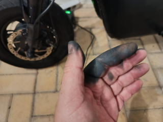
Very first thing were to remove one side of the tire, and for that I used that long tire dismantle tools. Then, I did pull the inner tube, cut it and removed:
1744292966782.png

To my amazement, the sealant inside were mostly dry!! So I need to replace the tire sealant after some months...1744293499532.png

Then I had to push the tire (was not hard) to have access to the hole for installed the tubeless valve:

1744293571848.png

The valve I installed this one from Aliexpress - is very small and probably the only one that can be used!!

I could install it without removing the tire, was not hard:

1744293742614.png

There is very small space on the rim and every time I want to inflate the tire, I need to bend a lot the valve, but works ok.

1744293818233.png

This tires I use, 3.00x8, are very strong, good and they are tubeless!! I bought them in Aliexpress.

I asked the motor seller and they told me that they didn't know if the rim would work for tubeless... but it works. And here putting the tire back on the rim:

1744293917035.png

There is an important trick to be able to inflate this tire as tubeless!!

After installing the tubeless sealant, we need to remove the inner valve to let the max air flow possible, then push a lot of the air in the hope the tire will get accommodated on it's place. Then install the inner valve and finally push the air until the tubeless tire seal and hold the air!!

VERY IMPORTANT, using a tightening strap at the middle of the tire, will force the laterals against the rim walls and that will finally make the tire to seal the air!!!

1744294476200.png

A failed attempt with a lot of sealant all over the place:

1744294796873.png

But after a few tries, it worked!! I am being using tubeless on the two wheels since 8 months ago and I had no issues at all!! Very happy with it!!

1744294867266.png
 
FWIW, if the sealant used is Slime brand, it tends to clump up into chunks after a few months (or less, depending on temperature/etc) from churning inside the tire all the time. It also makes it impossible to patch a tube roadside without also carrying cleaning supplies / tools to get all the slime off the area to be patched and keep it from leaking out under the patch while applying the patch, which keeps the patch from sticking.

Those are the main reasons why I stopped using it in my tires, except for instances where I may put some in when a slow leak (but fast enough to not make it home just reairing it) develops (usually from a goathead or paloverde spine or steel bit from steel-belted tire debris) so that I can get home, then wash out the tube, dry it, and patch it for later use (replacing the tube in the meantime).


Never tried tubeless sealants, but I expect any sealant made the same way slime is will fail the same way slime does.


Mostly I depend on enough rubber thickness to keep pokey things from touching my air, by using thick tires and thick tubes and an old tube or two between those for extra thickness.... it works pretty well, less than one flat a year nowadays.

With the SB Cruiser trike doing any roadside rear wheel work is very difficult, so anything that helps me avoid doing that is useful...but when I do have to fix a hole, I'd like to know the patch will stick even on a big hole that sealant can't possibly help with. ;)
 
Because on this Fiido Q1S, with dual motors and using a lot of power compared to my EBike, the UART communications to VESC here gave a bit of errors and so the data on the display suddenly fail / kept out on synchronization. So, I decided to move to CAN communication and is way better (still a tiny bit of packets that are not received but almost impossible to see).

Here is the latest state of my Fiido Q1S. Note that the display image looks pixelated but that 's because it was recorded very near, in real usage it is way far from my eyes and is great!!

 
Last edited:
So, I decided to move to CAN communication and is way better (still a tiny bit of packets that are not received but almost impossible to see).
Are you using a shielded cable between the two, with the shield grounded at only one end? And the shield around only the communications wires and their ground wire (which should be separate from the system power ground wire). That may help.

Using twisted pairs for the comm wires can also help, each comm wire with it's own ground twisted with it.
 
I had issues with throttle and took some days to figure out the issue. I though my ESP32-S3 board were partially burned or some deep issue with the CircuitPython firmware. In the end, I could understand the issue were about high voltage on IO pins that were changing the analog signal of the ADC input of throttle signal. The CAN module must be powered with 5V and says the IO pins can work with 3.3V but I think that was causing the issue, driving the ESP32-S3 IO pins over the 3.3V.

To solve the issue, I had to use resistor to adapt from 5V to 3.3V. It is working, perfect results, although I am not sure everything is working electrically as expected. Maybe in future I should try to find a CAN transceiver module that really works at 3.3V.

Now there are no erroneous values read from VESC, everything seems perfect.

Final schematic:
1744806019088.png


And the final design for the display is this:

1744807341447.png
1744807362378.png

Are you using a shielded cable between the two, with the shield grounded at only one end? And the shield around only the communications wires and their ground wire (which should be separate from the system power ground wire). That may help.

Using twisted pairs for the comm wires can also help, each comm wire with it's own ground twisted with it.

This is DIY, I am doing all this kind of quick. The only care I do is keeping the wires short. Look how ugly (but fully functional) is current board, based on that schematic:

1744805688428.png
 
Last edited:
If it works, it works, don't break it. But at some point I would design a pcb for it.
Next build will probably be an old Xiaomi M365. I guess is just the same motor controller board, with one brake and one throttle. The same wireless display, the same wireless lights. But I need to build a wireless power switch, as I will use the original battery and not one with the same BMS I use on this Fiido Q1S, that power is turned on/off controlling a little relay / physical switch.

So yes, I guess and could design a PCB. Maybe.
 
If you need to, they make 5v-3.3v level translators. I haven't tested them yet but I picked some up when I got an assortment of ESP/nano/etc MCU boards to experiment with a while back.

They were called "TXS0108E 8 Channel Logic Level Converter Bi-Directional High Speed Full Duplex Shifter 3.3V 5V", and I think at the time they cost about 50 cents each IIRC.
1744865758674.png

I also got a few much simpler "4 channel IIC I2C Logic Level Converter Bi-Directional Module 5V to 3.3V" that were made from what I think were individual transistors instead of an IC chip; they were even cheaper, maybe 10 cents each or less; don't recall for sure.
1744865704512.png
 
If you need to, they make 5v-3.3v level translators. I haven't tested them yet but I picked some up when I got an assortment of ESP/nano/etc MCU boards to experiment with a while back.
Thanks, but I found a 3.3V CAN transceiver, so will be a direct exchange to the other. This is still small and cheap:

1744973140233.png
 
I did a few changes recently to my Fiido Q1S electronics. I was having some issues: throttle signal picking noise and sometimes the motor would stop until I cycled the power.
All this after I moved the 2x VESC Makerbase 75200 to inside of the tube where the original battery and motor controller where. My plan where to free some space on the middle of the frame and I think I will not change the electronics more. Still, the main board + display board are easy accessible for some firmware improvement if needed.

Here I placed one VESC Makerbase 75200 on top of the other. Had to make some hole on the frame for the cables:

1758474908870.png

So, throttle signal picking noise, I though it could be because of ESP32-S3, it is a known issue of using ADC2 channels. So I decided to change to ESP32-C3, because is newer, uses way less power (good to avoid noise due to wires on this DIY build), is the most cheap ESP32 and I already use it on the display.
I also decided to build again the board. Here the schematic. I think the total cost in components for this main board is about 10€:

Schematic, firmware, etc, I share everything as OpenSource on github:


1758474627297.png


And picture of the board during the build, where I had yet to install the SN65HVD230 CAN module.
Not represented on the schematic, but I use a second throttle, it is just the same 2 resistors and 1 capacitor circuit, connected to another pin of ESP32-C3.
The green module DC-DC board that downs the 72V to 5V:

1758474048906.png

And here the other side of the board and the black board with the ESP32-C3:

1758474888081.png

And in the middle of the process of testing everything before final assembly. I did the battery with a handle, to be easy to remove and charge it on different place where the scooter is stored. Sometimes I charge inside coffee shops or restaurants, on my adventures.

1758475161921.png


So, the throttle picking noise was solved, although I am not sure if the issue were with ESP32-S3, my guess is more with some long cable or damage connector.

About the motor stopping suddenly: after installing the VESCs inside the frame, the CAN cable to the main board had to be longer. So, the motor would stop even faster...!! The issue were noise on CAN bus, I had to remove a CAN termination resistor from the "middle" VESC and install it and the end, on the CAN module SN65HVD230. I also had to lower the CAN frequency from 500Khz to 125Khz and then finally I had not more CAN communication errors!!

Another issue I had, I made a short circuit when inserting the charger connector. I was very tired and I started to insert it kind of at a 90 degree angle - the connector just burned and my finger were also burned but luckily recovered after 2 weeks:

1758475860449.png

So I decided to go with a really good connector, LP16.
There are a few advantages:
- the battery power pins are not easy accessible, so hard to make a short with something metalic
- guided position to insert, to avoid the short I did on the basic cheap connectors
- click connection so the charger will not disconnect by mistake, and make sure the scooter fully charges during the night

I bought the connectors on Aliexpress:

1758475409575.png
 

Attachments

  • 1758475824414.png
    1758475824414.png
    1.7 MB · Views: 3
Last edited:
And here the other side of the board and the black board with the ESP32-C3:
You may already know this, some of those ESP32-C3 supermini's had very poor RF design, documented here;

Solution, DIY antenna;

Hope your fingers heal well.
 
You may already know this, some of those ESP32-C3 supermini's had very poor RF design, documented here;

Hope your fingers heal well.
Thanks.
Yes, I already know that issue. Everything works well, I use the wifi for ESPNow wireless communications with the display, lights and battery BMS on/off switch.

Sometimes I carry my little daughter on the Fiido Q1S. This summer I did that a few times, once I even put some foam on the handlebar to avoid is face hit against it hard, as we did a few kms on mountains to enjoy the green environment, the sun and wind, while going swimming to a river.

1758485321101.png

Daily, after 8h in from of computer and riding home in car, I really enjoy to ride my Fiido Q1S and go to the gyms, in shorts and tshirt, getting to latest sun of the day. Then I back home and get the beginning of the night, and I travel over some nice roads with green and calm fields - but the gyms are packed with young generations and they use a lot electric scooters :) bought on local super markets.

1758485724130.png

1758485579007.png

1758485357718.png
 
and my finger were also burned
Oof, I've done that to a finger as well; 72v backwards was scary as shit, though mine didn't look quite as bad as that.

What kind of connector was on the charge cable before? I've pretty much stopped using any kind of symmetrical connectors for this kind of reason.
 
Oof, I've done that to a finger as well; 72v backwards was scary as shit, though mine didn't look quite as bad as that.

What kind of connector was on the charge cable before? I've pretty much stopped using any kind of symmetrical connectors for this kind of reason.
Like this:
1758579026636.png

And after the short, the metal parts just evaporated:
1758578990916.png
 
I wanted to access to my BMS battery data, as I was only using data from VESC. When I connect the charger to the battery, the VESC don't see the battery current that is charging.

My idea is to automatically detect when charger is connected: BMS battery current is negative + VESC battery current = 0 and motor speed = 0. So, I want my display to switch automatically to charging mode, showing me in big size the battery SOC and voltage, as also disabling the motor for security (don't want my kids to touch the throttle and run the motor, while the micro scooter is charging on the garage).

I also wish to compute the battery internal resistance + estimated time to fully charge.
The internal resistance, I already did this calculation on my previous C code for EBike, it is a good indicator of the battery health - so track new battery resistance and then actual resistance, will show us how bad battery degradation will be over time.

So now I can read my JBD BMS data over Bluetooth!! but to get that, I had to switch from CircuitPython to MicroPython!!

Thanks a lot to AI for helping with JBD BMS data reading, as also all the refactoring to MicroPython the code from the motor board as also the display!!

1759404882383.png

The display took me a few days to convert to MicroPyhton, even with AI - current state:1759404747640.png

I am investing all this because I decided to buy a similar micro scooter as Fiido Q1S, but a cheaper one easy to buy in EU from Aliexpress - I bought the iScooter i12 for about 250€ only (shipping included) and from a warehouse in Europe.
And for what I could understand this model or similar ones are also popular / easy to buy in USA.

This is a seated 12 inches wheel (but there is a version with 14 inches wheel - I bet it is the same frame) and full suspension.
DD hub motors, wheels, tires, rear shocks, front suspension, disk brakes, are equal / can be equal to the Fiido Q1S. The only part that is different is the seat, put I am pretty sure I can use the Fiido Q1S / monkey bike seat doing a small adaptation.

Here is a modded version from an user:

1759405894983.png


This micro scooter will be for my 15 years old son daily usage to go to school and gym. I don't want it to go fast, so I think I will keep using only the original rear direct drive hub motor. But sure, it will need more power, so I will install for sure the VESC + this DIY electronics and firmware. Then I will upgrade as needed, like adding an extra battery for more range.

A review of the original micro scooter:

 
Last edited:
Well, having the current firmware working with ESPNow for wireless communications with the display, the rear lights, front lights and BMS power switch board, is great. Now, I did a testing code using Bluetooth communication to read the battery data from the BMS JBD Bluetooth, but after joining this test code with the current code, the ESP32-C3 has not enough memory!! So I am back to ESP32-S3 Zero board that I bought here.

This is the current schematic.
I also corrected some swapped CAN TX/RX lines.
1759693364407.png

Here is the current firmware, working as expected on ESP32-S3. Again, I had to build MicroPython to add the CAN driver.
Here is the battery current read from the BMS JBD Bluetooth. NEgative when discharging and positive when charging:

1759693091218.png

I added the built MicroPython firmware with the CAN driver, here, including the instructions and the patch:

1759693274781.png
 
@casainho the frame of this scooter looks flimsy, if you plan to add a lot of battery make sure you add some reinforcements similar to the ones you did in your fiido q1s. Interesting project.
 
I am creating the screens and currently I have the charging screen with big battery symbol and animation:


1760681173117.png
 
First test with VESC. But after I got the motor running with the motor board, I connected the throttle and the brake sensor. How simple it is!!


Now it misses the wireless display and the wireless lights boards.

As I also reused an old battery from a Xiaomi scooter, I bought the Makerbase AntiSpark Switch V2, to power on/off the system. Later I will build the wireless communications to this power switch.

So this iScooter i12 i14 will be just a similar build to Fiido Q1S, in terms of the DIY OpenSource electronics and software.

1760905979732.png
 
Finally I finished the screens.
The Charging screen is entered or exited automatically when the system detects a charging current, as reported by the JBD BMS via Bluetooth.I can also manually enter or exit the Charging screen by pressing the brakes and holding the power button.
Finally, a long press on the power button (without the brakes) turns off the power and shuts down the system.


But I was having memory errors, I guess due to large fonts, on ESP32-C3, so I changed to ESP32-S3 Zero board. I do not expect to change any more the display hardware.

I plan to keep both main motor board and display board, using ESP32-S3 Zero board. For the front lights, rear lights and BMS battery power on/off, as also VESCExpress, I plan to keep using the ESP32-C3 SuperMini board.

My current display schematic:
1761519504810.png
 
I installed larger tires on iScooter i12, here the final result:

1762630765203.png

I had the help of my son, the one that will use i12, to change the tires and we were able to put them as tubless!!

1762630918786.png

1762631030789.png


Trying to find max motor current, I used a VESC command to set the motor phase current to 50A and 0 speed, and I waited 60 seconds to see the motor temperature rise rate. I seems good but in the end the motor was burned:

1762633819258.png

1762634023283.png

I took the magnets measures from this iScooter i12 original motor and they are:
- 22 m length of magnets (maximum available space would be for 30 mm).
- 1.5 mm height
- 10 mm width
- 40 magnets

Now compare with the magnets of the Lunyee motor I use on Fiido Q1S, dual phase motor:
- 60 mm length of magnets
- 3.0 mm height
- 10 mm width
- 30 magnets

So yes, I think the original motor is a bit weak.

In the end I decided to install the original geared motor from Fiido Q1S. It works well, has a good torque and I got a very high speed with the temporary 72V battery I am using. But it makes noise and does not brake/regen, and due to the gears, it is not so fast to react as a direct drive motor.


Today we got a nice sunshine and we used our scooter to go to gym as also go to shop to buy some food. My soon with the iScooter i12 and I with the Fiido Q1S.

This was the first time my son used the iScooter i12 and I hope he will keep using it with me on next month, since we will have some hollidays, free time go go slow.

Current motor on iScooter i12 is the geared motor original from Fiido Q1S, but it makes noise due to the gears, do not brake/regen and got hot after 3 kms at max speeds of 35km/h. Luckily, I already bought the 2000W Lunyee 72V direct drive hub motor I am using on Fiido!!

My plan is to have limited max speed of 40 km/h and some nice acceleration/torque, to have an agile and fun scooter for my sun to ride!!

1764519867166.png

1764519892674.png

I friend help me to install foot rests and I am using the same on both scooters - I bought this ones.
On iScooter i12, I am using a M12 threaded rod of stainless steel.

1764519989339.png

Having our feet of this foot rests and wider than on original scooter, is way safer and improves our comfort.

1764520030341.png

1764520189729.png
 
This micro scooter will be for my 15 years old son daily usage to go to school and gym. I don't want it to go fast, so I think I will keep using only the original rear direct drive hub motor. But sure, it will need more power, so I will install for sure the VESC + this DIY electronics and firmware. Then I will upgrade as needed, like adding an extra battery for more range.

A review of the original micro scooter:

Based on video review, which says the scooter has an aluminum frame and weighs 45 lbs, I bought one from Walmart for $250 delivered. A magnet sticks to the frame so it's not aluminum. I weighed it at 60 lbs.

IScooter's spec says it's aluminum frame, 55 lbs. I am a little disappointed thinking it'd be easy to lift into trunk of a car.

@casainho, does your i12 have aluminum frame?
 
Back
Top