casainho
10 GW
- Joined
- Feb 14, 2011
- Messages
- 6,058
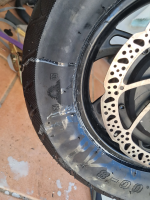
In August 2024, I was riding far from home and the rear tire got flat!! I were using inner tubes with sealant so I asked at a home I found, for help, to try to fill the tire with air in the hope the sealant would fix the issue. But no, was not possible!! I had to ask a long car ride to carry me and my Fiido Q1S.
Since it is very hard to remove the wheel and then remove the tire, I didn't carry with me the tools and an extra inner tube.
At home, I found the inner tube were pinched, with a few holes, so the sealant would never work.
I decided to try go tubeless, and that would be my very first experience with it. Tubeless means I would probably not had the issued I had and is also easier to repair because there is not need to remove the wheel!!
To test all this, I decided to install tubeless on my front wheel without removing it, trying to replicate the way I can do it outside home.
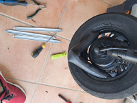
Very first thing were to remove one side of the tire, and for that I used that long tire dismantle tools. Then, I did pull the inner tube, cut it and removed:
To my amazement, the sealant inside were mostly dry!! So I need to replace the tire sealant after some months...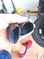
Then I had to push the tire (was not hard) to have access to the hole for installed the tubeless valve:
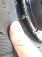
The valve I installed this one from Aliexpress - is very small and probably the only one that can be used!!
I could install it without removing the tire, was not hard:
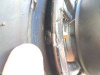
There is very small space on the rim and every time I want to inflate the tire, I need to bend a lot the valve, but works ok.
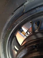
This tires I use, 3.00x8, are very strong, good and they are tubeless!! I bought them in Aliexpress.
I asked the motor seller and they told me that they didn't know if the rim would work for tubeless... but it works. And here putting the tire back on the rim:
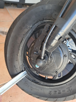
There is an important trick to be able to inflate this tire as tubeless!!
After installing the tubeless sealant, we need to remove the inner valve to let the max air flow possible, then push a lot of the air in the hope the tire will get accommodated on it's place. Then install the inner valve and finally push the air until the tubeless tire seal and hold the air!!
VERY IMPORTANT, using a tightening strap at the middle of the tire, will force the laterals against the rim walls and that will finally make the tire to seal the air!!!
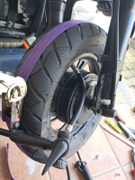
A failed attempt with a lot of sealant all over the place:
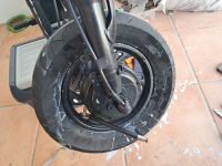
But after a few tries, it worked!! I am being using tubeless on the two wheels since 8 months ago and I had no issues at all!! Very happy with it!!
Since it is very hard to remove the wheel and then remove the tire, I didn't carry with me the tools and an extra inner tube.
At home, I found the inner tube were pinched, with a few holes, so the sealant would never work.
I decided to try go tubeless, and that would be my very first experience with it. Tubeless means I would probably not had the issued I had and is also easier to repair because there is not need to remove the wheel!!
To test all this, I decided to install tubeless on my front wheel without removing it, trying to replicate the way I can do it outside home.
Very first thing were to remove one side of the tire, and for that I used that long tire dismantle tools. Then, I did pull the inner tube, cut it and removed:

To my amazement, the sealant inside were mostly dry!! So I need to replace the tire sealant after some months...

Then I had to push the tire (was not hard) to have access to the hole for installed the tubeless valve:

The valve I installed this one from Aliexpress - is very small and probably the only one that can be used!!
I could install it without removing the tire, was not hard:

There is very small space on the rim and every time I want to inflate the tire, I need to bend a lot the valve, but works ok.

This tires I use, 3.00x8, are very strong, good and they are tubeless!! I bought them in Aliexpress.
I asked the motor seller and they told me that they didn't know if the rim would work for tubeless... but it works. And here putting the tire back on the rim:

There is an important trick to be able to inflate this tire as tubeless!!
After installing the tubeless sealant, we need to remove the inner valve to let the max air flow possible, then push a lot of the air in the hope the tire will get accommodated on it's place. Then install the inner valve and finally push the air until the tubeless tire seal and hold the air!!
VERY IMPORTANT, using a tightening strap at the middle of the tire, will force the laterals against the rim walls and that will finally make the tire to seal the air!!!

A failed attempt with a lot of sealant all over the place:

But after a few tries, it worked!! I am being using tubeless on the two wheels since 8 months ago and I had no issues at all!! Very happy with it!!


