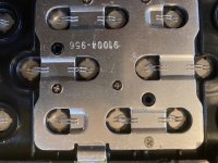
Molicel P42A, Sony/Murata US18650VTC5D in 14s5p battery packs sounds like a good deal?

I got four of these and three came with cells between 2 and 2.5v. They’re replacing the three low voltage batteries but let me keep them anyway. I plan to trickle charge them back to a useable voltage. How safe do you think these batteries with low voltage are to use?
 

Attachments

  • IMG_0297.jpeg
    IMG_0297.jpeg
    1.8 MB · Views: 4
That's odd. These are the brand new Sarcos batteries composed of 2170 cells.
My battery was 49.5v. Divided by 14 that equals 3.53v per group. Didn't bother to check individual groups.
 
Thanks to @daleconvert for figuring out the pins to wire color.

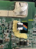
Looking at the PCB, the labels are:
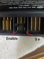
3v OUT - confirmed short blade marked in the pic is outputting 3v
ENABLE - need someone to confirm this one is the other short blade
SDA - I2C comm
SCL - I2C comm
ID - what is this? comm id for the I2C bus?

The green is marked ENALBE and the RED is 3v (can someone double check and confirm this please)

Turn on BMS:
I am guessing shorting the 2 short blades will turn on the BMS.

If you are NOT going to save the BMS, pls test this for us, using a momentary switch

connect the 2 short output in the pic below pls,
i.e. Connect ENABLE to 3V

maybe use crocodile clips and then connect that to a switch and short ENABLE to 3V
 

Attachments

  • sarcos_bms_5 pin.jpg
    sarcos_bms_5 pin.jpg
    195 KB · Views: 6
  • sarcos_pins_1.jpg
    sarcos_pins_1.jpg
    143.7 KB · Views: 6
Last edited:
Just discovered the same thing with the green wire lol, also was able to scrape off some of the yellow coating to uncover the lable for the black wire and it reads "5v BUT"...whatever that means.

I suppose Ill go ahead and try it and report back in a little bit.
That's odd. These are the brand new Sarcos batteries composed of 2170 cells.
My battery was 49.5v. Divided by 14 that equals 3.53v per group. Didn't bother to check individual groups.
can also confirm that all eight of my packs are at 49.5v and checking every p group, theyre all 3.53vs

Also on another note, anyone had any luck getting the bmses out non destructively? so far Ive had to tear them into two larger pieces to be able to get at the 6 gauge wire, my puny 80 watt iron doesnt make a dent in the solder joints, I should probably just get a bigger iron...
 
connect the 2 short output in the pic below pls,
i.e. Connect ENABLE to 3V

maybe use crocodile clips and then connect that to a switch and short ENABLE to 3V
Quick update, tried this nothing happened, mosfets remained open and the battery indicator bar and the button on top still do nothing, also tried a couple different combinations of 3v and "5v BUT" to different pins and still no dice...
 
I would assume that there is digital communication between the robot and the battery. Beyond my pay grade, though.
The batteries are above and beyond anything I've ever opened up.
So, of course, I bought another one. With the 5% discount on that $120 battery the average price of the two didn't hurt so bad.
I hope someone can figure out the bms. Those solder pads are so big. I have a big old American Beauty soldering iron, but I would be scared to melt those suckers.
 
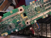
None of my irons worked 75w-150w with melted sold on tip of soldering iron. Then I tried a butane torch.worked I even tried my surface mount soldering gun. No melting of solder pads. I may try a DIY resistance soldering setup I have (thanks @spinningmagnets) it should get hot enough, i have plenty of braided copper wire to wick up the melted solder if it works. since I am sure the bms isn't salvageable now (on the first battery), I may just get the dremel out.
Later floyd
 
I found that the solder isn't conductive. if I had the negative probe on the solder lump or the positive probe on the solder on the cell taps I would get no voltage. Maybe the surface is oxidized forming a non conductive surface? Or maybe its an epoxy

later floyd
 
There is a sort of conformal coating over the entire board including the solder clumps, wasnt getting any readings from my meter till I realized that it was on there and scraped it off.
 
OK Thanks Duh You had mentioned the conformal coating much earlier in the thread.
Later floyd
 
I took off the cover and found mine was at 49.2V, with cell voltages at 3.52 volt,. So I didn't get low cell groups.

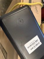
I couldn't find any hidden screws on the bottom of the case. Nothing under the label, I figure these round circles are where bosses were molded into the case? How did you guys get the cell assembly out? They're not held in with tape are they? That would not be very robotic.

IMG_5402.JPG
 
I haven't removed mine yet. but post 15 details how @daleconvert removed the cell assembly.
Later
floyd
 
Quick update, tried this nothing happened, mosfets remained open and the battery indicator bar and the button on top still do nothing, also tried a couple different combinations of 3v and "5v BUT" to different pins and still no dice...

How long did you short the 2 short blade pins for?
I remember reading the TI whitepaper and it mentioned a delay.

connect the 2 short blades and leave them connected and then press the batt level indicator switch, does it show a level?
Also, before you start charge your batt to 53v first, system is in sleep mode due to voltage probably.

so steps for someone who can test this for us:

1. Charge batt to 53 v (connect the POSITIVE charge wire to the positive fuse and NEGATIVE to negative blade in the bottom
I charged mine at 4 amp and it took around 4 ah to get it to nearly 53v

2. Short the 2 short blades in middle.
 
How to remove the two soldered spots in the middle that hold the battery in the case? The soldered connections on the side were easy to crack through
 
How long did you short the 2 short blade pins for?
I remember reading the TI whitepaper and it mentioned a delay.
Ended up leaving it connected for a good couple minutes, should have been adequate for any delay or timer
connect the 2 short blades and leave them connected and then press the batt level indicator switch, does it show a level?
nope, nothing seemed to change as far as I could tell

What I didnt think to check is as to whether the pins are atually providing 3v/5v with a multimeter, shouldve been the first thing I tried 😅

Also why charge the cells up to specifically 53v? curious as to whether there is any specific thing referencing 53v/~3.7v per cell (havent read the posted ti datasheet/manual yet) or if its just a hunch 😆

How to remove the two soldered spots in the middle that hold the battery in the case? The soldered connections on the side were easy to crack through
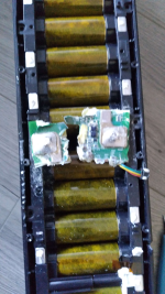
best method I found is to break the bms in such a way so you can get to this point
1715278429182.png
which then provides enough clearance for wire snips to reach the 6 guage and you can cut the remaining parts of the bms off
 
Last edited:
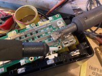
I had a massive iron used to build a leaded glass lamp many years ago. Also need a solder sucker. Add a little 60/40 solder to what's on the board, and its melting point comes down. The two spots in the middle are soldered to thick braided wires that go to the battery connectors. I used solder sucker and a lot of copper wicking braid to draw off solder.

Snip the other 12 wired connections to the BMS. Unplug three thermocouple connectors, and the small JST in the center. The BMS comes off, much worse for wear.

IMG_5405.JPG

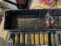
There are no visible screws holding the cell assembly in the case. I expect they used glue on the otherside. Now I have to go find my heat gun.
 
There are no visible screws holding the cell assembly in the case. I expect they used glue on the otherside. Now I have to go find my heat gun.
There is a some sort of brittle silicone holding the cells down but you can just pull them up without much issue, I didnt need to use a heatgun or the like, they just popped out
 
I used heat to soften the glue and the cell assembly came out with some prying, You can see the two power cables which were soldered to the BMS and had to be detached to let the assembly come off.

Bummer, what of robot is is held together with glue,
glue.JPG
There were two plates around the holes that lifted off from the heat.
holes.JPG
 
Last edited:
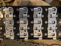
This is was the good part. The cells are wire bonded, and the wires may double as fuses. Another BMS could be attached and this ought to be one pretty stout battery. If one were looking to recover the cells, there's no nasty spot welds to rip out.
wire bonds.JPGfused wires.JPG
I don't have a use for a 14S pack this big. Probably just take out the cells and make mini packs.
 
Last edited:
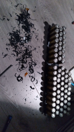
Recovering the cells is a massive pita btw, they are siliconed into the cell holders and it is a massive massive pain to remove said silicone
1715289667657.png
This took me nearly 2 and a half hours to get just one pack cleaned up, and thats not even accounting for cleaning the left over spots from the wires nor for getting the cells out of the pack in the first place. Found that using an ifixit spudger and opening pick seems to be the easiest way, and since they are both plastic theres no risk with shorting the cells out.

I understand why they did it as it would have not been optimal to have the cells be a friction fit into the holders nor would the fuses been enough structurally to hold the cells in place but its still quite annoying....and am looking at close to 18-20 hours to clean and harvest the cells out of just 8 packs...sigh
 
Recovering the cells is a massive pita btw, they are siliconed into the cell holders and it is a massive massive pain to remove said silicone
View attachment 352490
This took me nearly 2 and a half hours to get just one pack cleaned up, and thats not even accounting for cleaning the left over spots from the wires nor for getting the cells out of the pack in the first place. Found that using an ifixit spudger and opening pick seems to be the easiest way, and since they are both plastic theres no risk with shorting the cells out.

I understand why they did it as it would have not been optimal to have the cells be a friction fit into the holders nor would the fuses been enough structurally to hold the cells in place but its still quite annoying....and am looking at close to 18-20 hours to clean and harvest the cells out of just 8 packs...sigh
I'm sorry, but I do have to thank you for making me feel better about not getting these packs myself. I would have gone straight to cell recovery and been disappointed/frustrated.
 
I'm sorry, but I do have to thank you for making me feel better about not getting these packs myself. I would have gone straight to cell recovery and been disappointed/frustrated.
Haha I still do maintain that theyre worth it, if you dont value your time that is :LOL:

In all honesty I was fully expecting them to be potted or the such and in the grand scheme of cell recovery this isnt really all that bad
 
Back
Top