MOSFET cooling in commercial controllers; how do they do it?

Njay said:
strantor, I think you would be better trying to understand why a circuit doesn't work (and fix it) instead of jumping right away into something totally different. What have you learned from your previous circuit, besides that "it doesn't work"?...
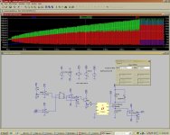
Well I beleive there was 2 problems in the previous circuit; #1 was that the MOSFET was too slow to turn off. easily taken care of by using a real gate driver. The current limiting was "working" but I was still getting amp spikes (see attachment). I beleive this was due to the current flowing through the diode not being taken into account. The only way (apart from using a hall sensor) I can think of to get a measurement of the current in the the motor and in the diode concurrently is to put the sense resistor on the same side of the switch and in the loop with the motor & diode. I don't know how to do that with high side sensing. So I went to low side sensing/high side switching. If you have any insight I would be glad to hear it.
 

Attachments

  • motorcontrolcircuitsim3.JPG
    motorcontrolcircuitsim3.JPG
    190.9 KB · Views: 218
Measure current on the low side switch should be enough, because the motor current won't be higher than that. It will flow for more time, but the peak won't be higher than the switch's peak. The limiting mechanism must be fast enough, of course. Correct me if I'm wrong...

Turn on-off the MSOFET also generates some oscillations on the shunt voltage; BigM already suggested filtering the shunt's output.
 
Njay said:
Measure current on the low side switch should be enough, because the motor current won't be higher than that. It will flow for more time, but the peak won't be higher than the switch's peak. The limiting mechanism must be fast enough, of course. Correct me if I'm wrong...

Turn on-off the MSOFET also generates some oscillations on the shunt voltage; BigM already suggested filtering the shunt's output.

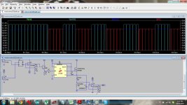
That's what I thought at first as well but what I saw in the SIM is that no matter how fast the MOSFET opens, if the current is only being sensed when the MOSFET is ON, it will switch on every cycle and abruptly shut off (if it sees the current is >limit as soon as it switches on), causing a spike, and additional losses. With the high side switch, (because the current flowing in the diode is the the same as what will be flowing through the MOSFET if it switches) it knows already whether to switch on or not. You can see in this closeup that it goes through 5 PWM periods where it never switches on
Dark blue= motor current
Red = diode current
light blue= gate drive voltage
senseres3.jpg
 
bigmoose said:
The NTE534 is open collector design and is a little slow, about 3 or 4x what I would like to see. It's output impedance is too high with the open collector for fast switching.
I bought this opamp (http://www.ti.com/lit/gpn/THS3202)
I picked it because of high slew rate and high current output. after I already ordered it, I noticed that it was a current feedback amplifier. Wikipedia makes me think it might still work for me:
In simple configurations, such as linear amplifiers, a CFA can be used in place of a VFA with no circuit modifications, but in other cases, such as integrators, a different circuit design is required....CFAs can be orders of magnitude faster than VFAs. With CFAs, the amplifier gain may be controlled independently of bandwidth...Disadvantages of CFAs include poorer input offset voltage and input bias current characteristics. Additionally, the DC loop gains are generally smaller by about three decimal orders of magnitude. Given their substantially greater bandwidths, they also tend to be noisier

What do you think? Will this work for me? or should I get something else?
 
Back
Top