Some thoughts below; dunno if any of it is helpful.
Quite heavy, around 150 kg, with bike, gear, batteries and all. The motor is a knockoff G062 6T, I rewound it with 220C wire to handle all that extra load. I get pretty tired of pedaling up the hill every 20 minutes, so 20 minutes on, 5 minutes off, repeat.
I am not sure I understand--you go down the hill then right back up the same hill immediately? At what speed? (the speed, weight, and slope are all needed to find out how much power it takes to do the job).
Batteries are two 15 AH generic li-ions in parallel, with a hefty diode to prevent cross charging.
Note that if there are diodes between the controller and the battery, the battery cannot act as a damper for any kind of voltage spikes that might occur.
There are various things that can cause the motor to generate voltage spikes; the most common is spinning as a generator (which shouldn't happen with a geared hub that has a clutch).
For instance,if you ever ride *down* that hill at a faster speed than the system could power you on a flat road, and the motor gets spun up (such as if the planetary's clutch sticks or if it doesn't have one), the voltage produced by that could be higher than the controller can take, and can damage the parts of the controller that are on the battery bus. It might not be catastrophic damage, but it could be cumulative until it fails.
As long as the freewheel/clutch inside the motor prevents the motor from being spun up that shouldn't be an issue.
but it can also happen from being switched in certain ways, if ther'es enough inductance the collapse of the current flowing thru the coils could generate quite a voltage spike, which has nothing to damp it without the battery being directly attached.
So...if it's possible I'd recommend directly parallelnign the batteries without the diodes. If they are identical and at the same state of charge that won't be an issue. If they're not identical then "it depends" on the differences whether there are any potential issues. (usually, there aren't). There *are* differeces in BMS designs that might mean you need to disconnect charger input paralleling while riding and disconnect discharge output paralelling while charging.
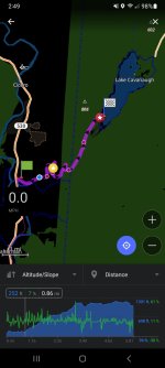
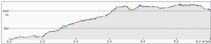
At points the road is up to 70% grade, at which I hop off the bike and walk while it pushes itself.
Hmm.
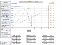
If I simulate even a 50% grade with a 48v phaserunner (closest to VESC), and a different bafang geared hub (didnt' see yours in the list), I get essentially no progress uphill at all, and rapid overheat of the system. I'm pretty sure the numbers below the graph are wrong, "blown" by the situation placed upon the components.
Motor Simulator - Tools

Trying to use the sim with "unlimited" controller, battery, and the biggest motor there to find out how much power it would actually take to go up that kind of slope with that load, I get numbers in the 7-10kw range for power used, and only speeds of a couple MPH, which makes everything worse. I don't think any of the parts you have in the system could handle that....even if the numbers are off by half, I have a feeling that the system is being overloaded by the hill(s), and that overload may be damaging things that cause later failures.
Might not have anything to do with the issues, but something to look into.
All the controllers seemed to fail randomly, the VESC failed after a pothole shook it, the no-names just went poof without apparent cause, and the longest lasting one (7 months) failed due to poor circuit design. The only controller that I could do an autopsy on had a failed microprocessor,
Failed MPU usually means that something sent a voltage into it to kill it, and that usually means either a phase/hall short that sent phase (battery) voltage into a hall signal line and thus into the MCU, or the battery-to-low-voltage converters failed and passed a high voltage into the MCU. The latter failure can happen if voltage spikes occur that aren't absorbed by the battery (which it can't do if ther'es a diode between it and the controller).
everything load-bearing was pristine, FETs, shunts and all. I checked my phases on the motor for shorts, which there was none. ~300 milliOhms from all phases to each other.
Just curious: What kind of meter was used to do the phase-to-phase check? (a regular multimeter doesn't go low enough to do this; I have a DE5000 that can do it with some motors)
And were the phases disconnected from each other inside the mtoor at the wye connection point? (if not, that is an alternate resistance path and can affect the readings).
I have run my motor sensorless due to the low quality halls failing repeatedly,
Even the low quality clone sensors don't normally fail repeatedly. If this is happening, there is probalby something that is causing them to fail--overheating, voltage spikes (either direct on the supply line or the signal lines, or induced voltages on these from high currents on the phase wires that run in the same cable with the hall wires), or something else.
Note that geared hubs can easily overheat because there are multiple airgaps between the heat-generating windings and the outside air, and it can take a long time for that heat to get out of the motor. Under high load the motor can overheat before the outside even feels warm.


")