Motor comparison spreadsheet

crossbreak said:
what's wrong with excel? When writing a simulator, it should be easy to write a simple file parser as well.

Instead of excel, we could use our own XML format. but at this stage i see no reason why. It works as intended, doesn't it?

It would be good to be able to select and order the motors to be compared? No?
 
Miles said:
Scrapping the old sKm and replacing it with the Km²/M values and calling it sKm² : ) . Using Km² instead of Km in the two power columns.
great!

Miles said:
It would be good to be able to select and order the motors to be compared? No?
sure this would be great. but this includes writing some sort GUI...which might be a lot of work. As long as there is no proper code base for the simulator, i dont see the point in this.

I am also not sure about which language to use for the simulator. ATM simply use excel, but this will be a dead end when starting to simulate drive cycles. Matlab is really handy in use (it comes with functionality to view 3D map data etc), but i am sure not all who want to use or contribute are willing to download or even pay for it. There are alternatives to Matlab, though, which can execute Matlab code.

ATM i started moving on with matlab, as i think i can port the code relatively easy if there is a demand for that.
 
this is what the simulator looks like atm


Code:
clear;
close all


%%value for TC4080
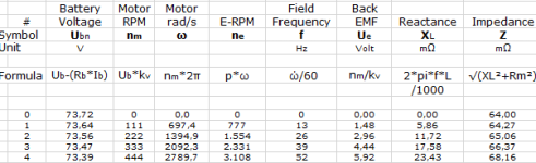
kV = 9.3; % back EMV konstant of motor in rpm per Volt
kT = 9.5492966 /kV;
L= 0 /1000000 ; % motor inductance in Henry
m_R = 89 /1000; % motor resistance in Ohm
m_eddy_trq = 0.00031415927; % eddy current torque in Nm per rpm
m_hyst_trq = 1.66; % hysterisis torque in Nm


m_cur_lim = 150; % maximum allowed motor current in Ampere

bat_volt_nom= 48; %the unloaded nominal battery voltage

m_rpm_length = 100;  %% length of  motor speed vector
m_rpm = 0:kV*bat_volt_nom/m_rpm_length:(kV*bat_volt_nom);  % motor speed vektor in rpm

bat_volt = bat_volt_nom*ones(1,max(size(m_rpm))); %% vector of actual loaded battery voltage over motor rpm
bat_cur_lim = 50;

m_mags = 46; %% motor poles or number of permanent magnets
m_frequ = m_rpm*m_mags/2/60;  % commutation of field frequiency in Hz over rpm
m_volt = m_rpm/kV; % back EMF Voltage in Volt-RMS of the motor over rpm
m_Xl = 2*pi*m_frequ*L; % motor reactance over rpm
m_Z = sqrt(m_Xl.^2+m_R^2); % motor impedance over rpm
c_volt = m_volt./2+sqrt(m_volt.^2./4+m_Z.*bat_volt.*bat_cur_lim);%*m_Z);_ % controller output voltage in Volt-RMS

for i=1:m_rpm_length+1
    if  c_volt(i) > bat_volt (i)
        c_volt(i) = bat_volt(i);
    end
end

m_cur = (c_volt-m_volt)./m_Z;

for i=1:m_rpm_length+1
    if  m_cur(i) > m_cur_lim 
        m_cur(i) = m_cur_lim;
    end
end

duty = c_volt./bat_volt*100;
bat_cur = m_cur .* duty ./100;
bat_power = c_volt.*m_cur;
bat_power2 = bat_volt.*bat_cur;
m_torque = (m_cur)*kT - m_eddy_trq*m_rpm -m_hyst_trq;
m_power = m_torque .* m_rpm /9.5492966;
eta = m_power./bat_power*100;


%% Vehicle
v_dia= 26;  %% wheel diameter in inch
v_circ = v_dia *0.0254 *pi; %% wheel circumference in meters
v_reduction = 1; %reduction ratio of the drive
v_rpm = m_rpm/v_reduction;
v_spd = m_rpm/60 * v_circ; % vehicle speed in meters per second
v_kph = v_spd *3.6; % vehicle speed in kph

v_cw = 0.7; % Drag Coefficent
v_A = 0.8 ; % Face Area
v_cwA = v_cw *v_A; % Combined Coefficient cwA=cw*A
v_rho = 1.275; % desity of air

v_drag_force = (v_spd.^2) .*v_rho .*v_cwA ./2;  % drag force in newton: ?*cwA*(vms)²/2 
v_drag_power = v_drag_force .* v_spd;           % drag power in Watt

v_drive_torque = m_torque* v_reduction;         % drive torque in Newton Meter
v_drive_force  = v_drive_torque /(v_dia *0.0254/2); 

%% Plot
x = m_rpm;
y1 = eta;
y2 = m_power;
y3 = duty;
y4 = v_drive_torque;

figure;
grid on;
%grid minor;
ylabel = ('gude');
ax1 = gca;

%get(ax1,'Position');

set(ax1,'XColor','k',...
    'YColor','b',...
    'YLim',[0,100],...
    'YTick',[0, 20, 40, 60, 80, 100]);


line(x, y1, 'Color', 'b', 'LineStyle', '-', 'Marker', 'none', 'Parent', ax1)
str2 = '\leftarrow sin(3\pi/4) = 0.71';
text(-75, 60, 'efficiency','Color', 'b')
text(8,115,['\fontsize{12}{\color{red}\epsilon:= zf}'])


ax2 = axes('Position',get(ax1,'Position'),...
           'XAxisLocation','bottom',...
           'YAxisLocation','left',...
           'Color','none',...
           'XColor','k',...
           'YColor','r',...
           'YLim',[0,3000],...
           'YTick',[300, 900, 1500, 2100, 2700],...
           'XTick',[],'XTickLabel',[]);
line(x, y2, 'Color', 'r', 'LineStyle', '-', 'Marker', 'none', 'Parent', ax2)
text(-75, 60, 'power out','Color', 'r')


ax3 = axes('Position',get(ax1,'Position'),...
           'XAxisLocation','bottom',...
           'YAxisLocation','right',...
           'Color','none',...
           'XColor','k',...
           'YColor','g',...
           'YLim',[0,100],...
           'YTick',[0, 20, 40, 60, 80, 100],...
           'XTick',[],'XTickLabel',[]);
line(x, y3, 'Color', 'g', 'LineStyle', '-', 'Marker', 'none', 'Parent', ax3)
text(75, 25, 'duty cycle [%]','Color', 'g')

ax4_lim = 200;
ax4 = axes('Position',get(ax1,'Position'),...
           'XAxisLocation','bottom',...
           'YAxisLocation','right',...
           'Color','none',...
           'XColor','k',...
           'YColor','c',...
           'YLim',[0,200],...
           'YTick',[20, 60, 100, 140, 180],...
           'XTick',[],'XTickLabel',[]);
line(x, y4, 'Color', 'black', 'LineStyle', '-', 'Marker', 'none', 'Parent', ax4)
text(-75, 35, 'torque [Nm]','Color', 'black')
text(150, 150, 'TC4080','Color', 'black')

file.php
 
i'd add the formula to the headings like i did in the excel version of the simulator.

After all, i think we have all the necessary columns. but would be nice to make it a "standard" so i can write my parser :)
 

Attachments

  • coloumn.png
    coloumn.png
    6.5 KB · Views: 2,219
Great stuff Miles and Crossbreak.

Crossbreak, I know I'm jumping the gun, but how hard is it right now to get to the graphs like above? I'm reorganizing my battery pack right now, and I'm trying to understand how big a hit in efficiency I am taking by running HubMonster at such a high voltage. Seeing graphs with a 200A and 250A battery limit at 74V vs 115V would be a big help in deciding my pack arrangement, because after some speed runs I would change some connections and go to a lower voltage if it makes a significant difference.
 
Motor inductance definitely affects losses in the controller, but I don't know about in the motor....any effects on the motor have been too small to notice.
 
crossbreak said:
it tunes the shape of the power curve. this is not to small to notice, at least for a motor like the hubmonster, which may have 50µH

a bare graph that is based on incorrect formulas wont be much help

If I could ever find my inductance meter that vanished almost immediately after delivery I could verify, but going from memory I think my son measured the phase-to-phase inductance at 75µH for HubMonster.

Maybe we're not talking about the same thing, but if you take to of the same motor wound to different Kv's, simply changing the voltage and current in the correct ratio makes their performance curves virtually identical, but inductance is quite different.
 
I'm struggling to keep up with this... What does Km^2 indicate that Km does not? What happens with motors with a Km less than 1? Km^2 will be smaller than km.

Going back to the first post in this thread and following the link to where the discussion of km originated, Luke explains km as a measure of the amount of mechanical power a motor can produce for a given amount of heat (loss) produced.

Following the link to the motioncomp document, it states:

"Motor Constant is a figure of merit used to compare the relative efficiencies and output
power capabilities of different motors. Km defines the ability of the motor to transform
electrical power to mechanical power."

The logical extension was sKm, which simply divides by motor mass to give a performance-to-weight ratio.

Considering that, a motor with and without a gearbox *should* have different Km and sKm. For two motors in parallel I suspect something is going wrong with the calculation - some loss of other is not being scaled linerarly.

I could be wrong - hence I would like to know what squaring motor efficiency and then dividing it by mass achieves? :)
 
It's not just about the parallel motor thing. If you compare two motors of the same model, one of which has double the stack length of the other then, ignoring the affect of the end turns to the resistance values, the Km value will change by a factor of √2

Km scales quadratically.
 
Fair point. How then do we reconcile that failing with that Km appears to be an established industry metric for motor performance? Is industry wrong? Have we, as a group, misinterpreted it somehow?
 
I wouldn't say it's a failing. There are other rating systems which aren't linear. Decibel scales, for instance.

The problem only arises when we divide by mass.
 
I've rearranged the order of entries into two groups. Hub motors and everything else. Within the groups, entries are ordered by mass. This makes for some interesting comparisons.
 

Attachments

  • Motor Data V2.01.ods
    40.5 KB · Views: 52
  • Motor Data V2.01.xls
    155 KB · Views: 77
I suspect you guys are way ahead on this stuff :) In an attempt to improve my own understanding I've done a little background reading on Km, which I'll summarise in case it's relevant or helpful to anyone else in understanding this stuff.

Firstly, Km appears to be as common as Kt and Kv and is proportional to them (you can calculate Kt or Kv from Km). It's known as the "motor constant", but more commonly as the "motor torque constant".

I've seen it defined as:


motor torque(Nm) / √power(watts)

[https://en.wikipedia.org/wiki/Motor_constants & http://www.moog.com/literature/MCG/moapp.pdf]


motor torque / motor current

[http://web.stanford.edu/class/me161/labs/Lab06MotorConstants.pdf & http://www.micromo.com/technical-library/dc-motor-tutorials/motor-calculations]


torque sensitivity (Kt) / √ terminal resistance (Rt)

[http://www.electromate.com/db_support/attachments/Understanding%20the%20Motor%20Constant%20v2.pdf & http://www.globe-motors.com/dc_motor.pdf]


motor voltage / motor velocity (as = motor torque / motor current)

[http://www2.ece.ohio-state.edu/~passino/lab2_rotary_dynamics.pdf]


Descriptions of what Km is used for vary between comparing the capability (or "size") and/or efficiency of different motors, being a tool to select a "best fit" replacement motor for an application. A "ratio of the motor torque (mechanical power) to motor input power (electrical power)", "the only parameter you need to determine the capacity and efficiency of a motor". The torque produced for 1 watt input power. "For the same size motor the higher the Km, the more efficient the motor is."

All sources stress that motors compared must use the same units and that Km is unaffected by winding configuration, as long as winding area is constant.

I still cannot grasp the exact nature of Km. It doesn't help that the various sources inter-change "power" and "torque", but I suspect this is possible because of the proportionality of Km, Kt and Kv. I think it does allow meaningful comparisons of motors of different windings, different sizes and different operating voltages/currents.

I agree that dividing it by mass is probably flawed because, unless I am mistaken, it is a unitless ratio (dimensionless). It would be like diving efficiency by mass (%/kg), which wouldn't tell you much about specific power, perhaps just that efficient motors are heavy.

Km also doesn't take into account any thermal effects on motor performance capability, but since it encompasses efficiency, perhaps it indicates it (but neglects core losses?).

I guess continuous power density would be a useful comparison for motor performance "The continuous power density is determined by the product of the continuous torque density and the constant torque speed range of the electric machine.", but you can't derive it from simple motor measurements...

Over to you cleverer chaps ;)
 
Punx0r said:
I agree that dividing it by mass is probably flawed because, unless I am mistaken, it is a unitless ratio (dimensionless). It would be like diving efficiency by mass (%/kg), which wouldn't tell you much about specific power, perhaps just that efficient motors are heavy.

I think dividing by mass is a valid operation, in as much as that all we need is a relative scale. The problem with dividing Km by mass is that Km increases quadratically (inverse) while the related mass increases linearly. Squaring Km is just a trick to correct for this.
 
Give me Kt or Kv, Rm, core loss info, inductance, and mass, then I've got everything I need. Actually, I prefer physical dimensions to mass, since fitting a motor is more difficult than carrying it, and dimensions correspond pretty well with mass anyway.

Excluding core loss from the calculation of Km is a major shortcoming. How can something be referred to as the "motor constant" without core effect info? Leave it to manufactures to come up with something like that so they can hide cheap steel and/or extreme pole counts.
 
John in CR said:
Give me Kt or Kv, Rm, core loss info, inductance, and mass, then I've got everything I need.
Sure. But how do you compare different motors in a simple way? You can't integrate core loss into Km because it varies with the rotational velocity. We've included this as separate values. Maybe we could integrate it into the power side somehow?
 
Punx0r said:
The torque produced for 1 watt input power. "For the same size motor the higher the Km, the more efficient the motor is."

Example: Crystalyte 20mm SAW (Rm = 0.231 mΩ, Kt=0.7, Km = 1.456, Km² = 2.121):
I²R loss is 1Watt, so I = √(1W/0.231 mΩ) = 2.08 A. With a Kt of 0.7, it does 1.456 Nm of torque, the same value as Km. This is exactly how Km is defined: The output torque of a motor in Nm at a copper loss of one Watt.

Punx0r said:
I'm struggling to keep up with this... What does Km^2 indicate that Km does not? What happens with motors with a Km less than 1? Km^2 will be smaller than km.
If you want to compare 2 different motors, producing the same torque, Km does not tell you much. A motor with double the Km does not have half of the loss, as pointed out some posts ago. But a motor with double the Km² will have half the I²R loss. So, using Km², you can compare different motors for a given Torque demand rather than comparing different Torques for a given acceptable I²R loss.

If you want to compare different drives with different reduction ratios, you have to multiply Km and reduction ratio before squaring it. If you do not get a figure larger than 1 after doing so, then your drive is probably too weak to move a vehicle :D
Actually there is no problem in Km² values being smaller than Km values, you can still use them to compare different motors for a given torque demand.

Example: Crystalyte 20mm SAW, you need 1Nm of torque. I²R loss is I²R = (T/Kt)² * Rm = (1/0.7)² *0.231 = 0.471 W. As you can see, this loss of 0.471W is the inverse of Km²: 1/Km² = 1/2.121 = 0.471
So: If you choose to use 2 of these motors in your vehicle, loss at 1Nm will be exactly half, as Km² is twice the value of a single motor.
 
Back
Top