Motor doesn't spin freely

Singularo

10 mW
Joined
Apr 21, 2020
Messages
22
I believe that I've blown a couple MOSFETs in my controller.
I turned my multi-meter on continuity test and plugged into my NEGATIVE anderson connector on my controller. I touched the BLUE phase wire on the controller and it beeped to let me know I have a blown negative MOSFET on my blue phase wire.
I plugged into my POSITIVE anderson connector on my controller, and touched the YELLOW phase wire with the black multi-meter rod and it also beeped.
This led me to believe I have a blown negative MOSFET on my blue phase wire, and a blown positive mosfet on my yellow phase wire.

I'm following this video here: https://youtu.be/lTssCn5YyTw?t=337

and he mentions to find the negative MOSFET on his controller, he puts his positive multi-meter rod into his anderson connector, and touches each of the MOSFETs with the negative on his multi-meter. I tried doing this, and it seems like I have 8 negative MOSFETs (here's a video of what is happening for reference: https://youtu.be/i2Gns-hkmrw).
To further complicate things, I tried doing the opposite: probing each MOSFET with the positive rod on my multi-meter, and only the first two MOSFETs beep.

My question is: why do I have 12 MOSFETs and the controller in the instructional video only has 6? How do I figure out which MOSFETs are positive and negative? Also, how do I know what specification of MOSFET to replace it with? I have a 36V 25A controller.
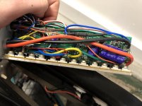
IMG_1918.jpg
 
I think I've found the datasheet for the MOSFET that's on my controller:
http://www.hymexa.com/asset/file/file/product/80V/HYG055N08NS1P&B%20datasheet%20V1.0.pdf

It says its 80V/120A and RDS(on) is 5.3mOhms. Do I need one that exactly matches this? Can the values be lower or higher?
 
Singularo said:
I believe that I've blown a couple MOSFETs in my controller.
I turned my multi-meter on continuity test and plugged into my NEGATIVE anderson connector on my controller. I touched the BLUE phase wire on the controller and it beeped to let me know I have a blown negative MOSFET on my blue phase wire.
I plugged into my POSITIVE anderson connector on my controller, and touched the YELLOW phase wire with the black multi-meter rod and it also beeped.
This led me to believe I have a blown negative MOSFET on my blue phase wire, and a blown positive mosfet on my yellow phase wire.

To further complicate things, I tried doing the opposite: probing each MOSFET with the positive rod on my multi-meter, and only the first two MOSFETs beep.

My question is: why do I have 12 MOSFETs and the controller in the instructional video only has 6? How do I figure out which MOSFETs are positive and negative? Also, how do I know what specification of MOSFET to replace it with? I have a 36V 25A controller.

IMG_1918.jpg

Replace with the same MOSFETS if you can, or similar specs. All should be the same make / model. Rated for Voltage, Amperage and impedende ( R Ds) . If you can find the right ones you may be able to just replace the compromised ( beeping ) ones.

Any beep or continuity from between the legs next to each other..... ( or blue yellow or green big wires.. no continuity is correct... ) to the ( batt plug ) means that fet is blown.. remove Fet and check the pads for continuity again and there should be none with the fets removed ( cut off board) tween legs or from pos/neg to phase blu yellow green... .

The 6 fet uses a pair (of fets) for each phase color... 3 ( phases), 2 ea = 6 total.. this is pretty much the minimum power handling controller available..

more fets spread the load and the manuf. goes to 12 Fet next.. and that is two pair ( a pair for each side of the phase, blue hi/lo, yellow hi/low, and green hi/lo) / phase ( 4 ea per phase, 3 phases, 12 fets:) ... Most. if not all ebike controllers use N gate Fets for simplicity all around.
 
I recently replaced some mosfets on my controller because it was hard to in the wheel with my hand (when the controller was plugged into the motor, of course). After replacing the mosfets, there's no more resistance in the motor when the controller is plugged in, but the motor still doesn't engage when I press the throttle.

I went back to test the resistance on each of the phase wires and noticed that when I have the positive meter plugged into my anderson cable, and the negative meter on any of the phase wires, the resistance is 0. When trying this in reverse, it seems like there is resistance. Could it be that I didn't solder the mosfets on properly? I figured if I didn't, I would it would still be hard to spin my wheel when the controller is plugged in.

Any idea what could be going on?
posi.jpg
nega.jpg
 
One of the things that can happen during FET failure is gate drivers can be damaged. That means the controller doesn't make the motor move because the FETs arent' being told what to do. Testing and replacing the gate drivers may not be nearly as easy as fixing the FETs; they're usually individual SMD components. :/


FWIW, the "O.L" doesn't mean zero resistance, it means more resistance than the meter can measure. (over load or over limit).

The other measurement looks like 3.22kohm, if I"m reading the meter scale (20kohm) correctly.

If all phases measure the same, without anything connected to the controller, the FETs are probably ok.
 
I remeasured the resistance today and it seems to be fine now! One thing that I was thinking that might be wrong is that my motor phase wire that runs from the controller to the motor is a bit weird looking and doesn't plug in all the way. It used to plug in fine, but one time when I was working on it, I plugged it in and it made a spark. Every since then, it's been tough to plug in. There is some silver coating on the inside of one of the male phase wires (that the other two doesn't have), and the female phase connector has a bit of discoloration.

The motor cable definitely doesn't go in all the way. Is there any way I can clean or remove this weird silver stuff that's on the inside of the cable?

motor.jpg
phase.jpg
 
That is metal spatter released as plasma from the arc-welding (spark) that happened. It used to be part of the connector pin itself, or the barrel.

You can carefully and slowly file it off with a very small roundfile for the part inside the female barrel, and with a very small roundfile or flatfile for the part outside the male barrel.

You don't want to damage the rest of the contact surface, or any of the small pins (hall sensors, etc) so try to only file at the bits that arent' supposed to be there.

FWIW, arcing causes RF which can cause electronics failures (FETs, gates), so I'd recommend ensuring good connections on all the phase wires.

Also, don't plug or unplug anything while the battery is connected / power is on.

BTW, whenever something tests differently one day than the next, you should look into why it is different. Because it means you could have something intermittent wrong somewhere, that will bite you later on, at the worst possible moment.
 
I replaced a bad mosfet on my controller, it lasted 3 months then the entire controller wound up going into a dead short. I then just replaced it since these 350 watt controllers are fairly cheap. The mosfet I used I got off Ebay.
 
I was going up a steep hill a few days ago, and once I got to the top my bike seemed to completely stop working (throttle didn't work, battery indicator stopped working). I immediately thought it must be the controller, so I went home and put a new one in.

Once I got the controller hooked up and plugged in the learning wire, the motor just made a buzzing sound without actually turning the wheel. Then I hooked up the throttle, and this is the result I got: https://www.youtube.com/watch?v=Izi1ppVSwzM&feature=youtu.be

When I press the throttle, the motor moves just a little bit, but it seems like it's trying really hard not to move. I unplugged my controller from the motor, and I noticed when I try to spin the wheel, there is a lot of resistance and the wheel doesn't spin freely like it used to. I once had a problem where when I plugged in my faulty controller, I would get this same behavior, but now I'm getting it even when the controller is unplugged.

Any ideas on what I can do next? Thanks!
 
The first most likely thing is the wires from motor to controller melted their insulation, and shorted together. That you can fix by replacing the whole cable from inside the motor to the controller connection.

The second is the actual windings inside the motor, and that you'll need a new motor for.

A quick first test is to cut the cable a few inches past where it exits the motor (to give you something to splice to), and if it spins freely it was just the cable. If not, then if you can get inside the motor you can cut the wires like an inch before they meet the motor windings, so you still have some colored wire on there, then put the motor back togehter (without the cable) and try to turn it. If it still wont' turn right it's the windings.


Eitehr way, the new controller is also probably blown.


If you have to ride hills like that, and it's killing your motor, you probably need a different system. Either one with more power / heat shedding capability, or one that goes thru the gears so you can shift down to low gearing and help the motor help you go up the hill easier.
 
Back
Top