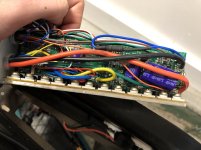
I believe that I've blown a couple MOSFETs in my controller.
I turned my multi-meter on continuity test and plugged into my NEGATIVE anderson connector on my controller. I touched the BLUE phase wire on the controller and it beeped to let me know I have a blown negative MOSFET on my blue phase wire.
I plugged into my POSITIVE anderson connector on my controller, and touched the YELLOW phase wire with the black multi-meter rod and it also beeped.
This led me to believe I have a blown negative MOSFET on my blue phase wire, and a blown positive mosfet on my yellow phase wire.
I'm following this video here: https://youtu.be/lTssCn5YyTw?t=337
and he mentions to find the negative MOSFET on his controller, he puts his positive multi-meter rod into his anderson connector, and touches each of the MOSFETs with the negative on his multi-meter. I tried doing this, and it seems like I have 8 negative MOSFETs (here's a video of what is happening for reference: https://youtu.be/i2Gns-hkmrw).
To further complicate things, I tried doing the opposite: probing each MOSFET with the positive rod on my multi-meter, and only the first two MOSFETs beep.
My question is: why do I have 12 MOSFETs and the controller in the instructional video only has 6? How do I figure out which MOSFETs are positive and negative? Also, how do I know what specification of MOSFET to replace it with? I have a 36V 25A controller.


