mounting hall sensors to R/C brushless motors

methods said:
I was under the impression that the standard method is trial and error. I am an EE but I could not tell you how to do it with a scope :D
There are several spradsheets around here to use... Keeping track is critical as it is easy to get turned around if you dont write down what has been tried.
There are also quite a few tips - little tricks that can get you to the correct configuration in only 2 steps if you can ... say.. get it to run smooth backwards.

Given that there are 36 possible permutations - 1 guaranteed to work, several likely to work - I usually get it within 6 tries.
I dont use current limiting but I do use a current monitor and a soft touch on the throttle.

I guess that is not saying much though since I dont use current limiting ever -> I figure the worst I can do is V/R :mrgreen:

-methods

Methods,

You surprise me. 6 of the 36 possibilities work, though 3 work in the wrong direction and 3 work in the correct direction. You can actually limit it to a maximum of 11 tries, by connecting 3 phases and trying all 6 hall combos. If that doesn't get it, then it will get a good reverse. On the good reverse, just swap 2 phase wires and try the other 5 hall combos again (the other 5 because you know the good one on the reverse can't also work in forward). Using this method you could lock the halls and change the phases in the same manner, but I find moving phases around more risky, so I stick with swapping the halls and try at most 2 combos of phase wires. The only confusing part is the false positives, ie spins right direction, sometimes very fast, but more noisy at start. Watching the current gives those false positives away right away.

John
 
hey,

i have a problem:

i would like to order a Brushless outrunner and a rc controller, but the controller has got a 6 pole wire for the sensoring..

Are there 4 hall sensors or what??? or 3?? how do you wire them
 
Benedikt,

I think that you will find that the controller has 5 sensor wires; +5V, 0V and three phase sensing wires (often yellow, green and blue, or labelled A, B C).

Most outrunner motors have 12 slot stators, so the Hall sensors need to be in every 4th slot. This gives a 120 degree spacing that will work with most controllers.

The wiring from the motor to the controller, once Hall sensors have been fitted, will be 3 phase wires (the heavy, high current connections) and 5 Hall sensors wires.

Hope this helps.

Jeremy
 
thx jeremy,

but i find that picture of the controller:
ezrun-150A-SL-03.jpg


here can you see that there are 6 poles in the plug... now im not sure.. is one pole, who isnt used??? but the wire has got 6 poles too??? :?: :?:

Sorry for my bad english: im 13 and from Germany
 
Hi Benedikt,

That looks like a Hobbywing car type ESC, so uses a Hall sensor connection that is different to the controllers we normally use here.

I think your best way to get the connection diagram will be to email Hobbywing and ask them. I have had a look at their website but have not been able to see the information you need.

Sorry this isn't more helpful.

Jeremy
 
Jeremy, i think all sensored rc esc use 6 poles.

i find a sensor for a brushless inrunner:
Graupner-Sensor-PCB-fuer-BL-PRO-DELTA-97286.1.jpg


it isnt from hobbywing, its from graupner...there are 6 poles too, bot only 3 sensors..i think that doesnt make sense. :?: :?:

i will send a email to some rc esc manufactors and see what they say :idea: :arrow:
 
i think hobbywing wouldnt awnser to me :evil: :evil: :cry:

so i buy a ready to use sensor and build it into my outrunner.. there is the wireing already :!: :mrgreen:

50623-lrp-2500_p1.jpg


and a temperatur protection is in it to :idea:

before i build it i will measure , how they are wired, then i write it here
 
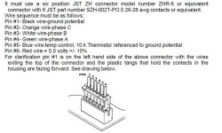
That explains the 6th wire - it's a temperature sensor!

Jeremy
 
THX!THX!THX!THX!THX!THX!THX!THX!THX!THX!THX!THX!THX!THX!

You are the best!! :D :D :D
 
That is the three sensor output wires coming from the hall sensors. If you are wiring up your own motor you will have to figure out what is A, B, and C phase yourself.
 
Benedikt,

You'll probably have to work it out by trial and error - just try combinations of the three Hall sensor wires (A, B, C) with the three motor phase wires.

There are some threads on here giving the sequences to check if you do a search for Hall sequences.

Jeremy
 
okay.....i will hope that it will not destroy my esc :cry: :cry:

edit: :idea: i think it will not destroy my esc:

in the usermanual is written: Trouble: the sensored motor doesnt work....solution: check the wire connection.

you have to read between the lines :idea: :idea: :mrgreen:
 
hey..... another question from me ...

can i put the sensors vertical into the ends of the slots?:

r0015056.jpg


sincerly

Benedikt from Germany
 
Ludo91 said:
Hi,
it`s time for me to buy the sensor. DigiKey run out of honeywell SS411, do you think this http://search.digikey.com/scripts/DkSearch/dksus.dll?Detail&itemSeq=97180852&uq=634347618920692357 will fit? I looked at all the specs and they seems to be the same, correct meif i`m wrong :)


"Item not found" comes up when i click the link :-(

KiM
 
AussieJester said:
Ludo91 said:
Hi,
it`s time for me to buy the sensor. DigiKey run out of honeywell SS411, do you think this http://search.digikey.com/scripts/DkSearch/dksus.dll?Detail&itemSeq=97180852&uq=634347618920692357 will fit? I looked at all the specs and they seems to be the same, correct meif i`m wrong :)


"Item not found" comes up when i click the link :-(

KiM

idk why, its working on my pc.... anyway AH175-PL-A-ADICT-ND is the product code so no problem to find them from here (digikey homepage w/ part search) .tnks! :D
 
HELP ME!! :lol: I thought i was sure about what 2 do about the switching sequence depending on hall sensor outputs but i`m not anymore! I found an atmel pdf with the correct switching sequence but hey! now I`m not sure anmore since a i foudn another one with another switching sequence :cry:

The motor is an htx 80-100 in its stock windings configurations, may anyone that has already put sensor on it tell me the correct hall sensors/ phases switching frequence?!

thanks!!! :D
 
Ludo91,
The hall sequence will depend on rotation desired & phase conection.
A-B-C is not defined on the turnigy motors in any way I can identify with consistancy.
finding the correct sequence by trial & error is really not difficult.

Just hook up your motor & halls....then test while keeping records of what is working.

I switch motor phase wires 1st to get a motor turning....once its spinning I can set the direction with a phase swap & matching hall swap.

possible motor phase combos
A-B-C
A-C-B
B-A-C
B-C-A
C-A-B
C-B-A
(these are mirrored by the hall wires for 36 possible connections....the correct one will be obviouse on the amp meter & by the sound the motor makes)
I rarley have had to make more than 2 attempts to get a motor spinning. Getting the timeing set correctly is another set of issues...if you have a Watt meter, just adjust for a low amp draw at 75% throttle settings as a base point.
 
isn`t that referred to a 3 phase commuting? I really think I am missing something, what I am trying to make is to make a commutation that is the same as shown at page 14 of this awesome pdf http://cache.freescale.com/files/microcontrollers/doc/ref_manual/DRM078.pdf
I can`t see how i could to that by trial and error so prabably I`m missing something really big of the whole thing :mrgreen:
Tnks guys! :D
 
Back
Top