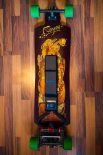
My build. Rayne Killswitch Electrified, 4KW Alien Components

Yeah. I wasted a few packs on the voltage meters from keeping them on even after riding. The voltage for those cells never came back. I'd just have the balance port accessible when you need it. Thats what I do now. I count on my esc to cut off but check it when I feel I'm close to done with the pack. A switch would be a nice feature too it should work.
 
superpef said:
Wouldnt a simple switch on one of the outermost balance leads of the pack allow to turn it off?
I went ahead and installed a switch into the balance lead wire and now have a CellLog onboard ready to read it while on the go.

I also finally incorporated the arduino nano and bluetooth wii nunchuk module into the setup. I can now chose between using an rc transmitter and the nunchuk without any hassle just switching cables. Of course bluetooth isn't as reliable of a connection as 2.4 GHz but after adding a bigger antenna I made out of copper wire I now have a solid connection. The nunchuk works great, it's just a different style of riding compared to using the rc transmitter. I choose the latter for speeding and quick transitions from slow to fast and the nunchuk for cruising and for its portability. Fits in every pocket and rests really nicely in the hand. Very low-key, too. I used toddy616's arduino code. Pushing and holding one button will hold the speed that is controlled by flicking the joystick up and down increasing/ decreasing speed incrementally. Pushing and holding the other button engages the brake as soon as the joystick is pulled down, with increasing braking force the farther the stick is pulled down. Like a brake pedal! AwwYeahh! Pics of the (at least for now) (finally) finished project to follow..
 
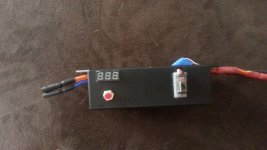
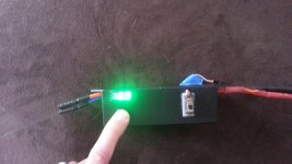
If you dont care about each cells voltage and just want a voltage reading you can use the setup i have. I just incorporated a simple digital voltage meter into my esc case with a monetary switch so it only uses power when i press the button. I just ran a small wire to the positive and negative leads of the esc.
 

Attachments

  • 20140325_110426.jpg
    20140325_110426.jpg
    294.1 KB · Views: 3,809
  • 20140325_110435.jpg
    20140325_110435.jpg
    320.3 KB · Views: 3,809
flex3269 said:
If you dont care about each cells voltage and just want a voltage reading you can use the setup i have. I just incorporated a simple digital voltage meter into my esc case with a monetary switch so it only uses power when i press the button. I just ran a small wire to the positive and negative leads of the esc.
Yeah that's another way to do it, anyway I thought the CellLog wouldn't hurt as it's pretty small in size too. It's glued to the esc's heatsink with hot glue.

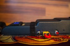
Here's everything crammed into the enclosure :mrgreen:
View attachment 2
IMG_6699.jpg
IMG_6697.jpg

[youtube]7Ravi7YoOX4[/youtube]
 
i will have 4 batteries so i was going with making a splitter for the balance leads on the batteries and one side will go to the lipo battery checker that read out the voltage like this: will use 4 one for each battery pack.
$_35.JPG


and the other half for charging.

i will also include a switch (either momentary or a regular switch) and it will only cost me $10
 
Hm, after extensive testing I revoke what I said about having a solid connection. The nunchuk has lost connection several times, especially when riding in the city center with more sources of interference. As I said I attached a copper wire to the antenna on the bluetooth module, but that doesn't seem to be enough. Any ideas guys on how to enhance a bluetooth signal? Would I have to enhance both transmitter (nunchuk) and receiver?
 
At first you can try with correct antenna length. Wave length for 2.4GHz is ~12cm, so use a 12cm wire. If 12cm is too long you can try with 6cm or 3cm. Be precise when cutting the wire.

EDIT: One more thing. 2.4GHz doesn't really like going trough material, so place the antenna outside. I have a Bluetooth module on my quadcopter. It works on 100m with regular smartphone. So it is a bit weird that your link is unstable on 2 meters.
 
Yeah there are obviously big differences in bluetooth connection strength amongst different devices. I guess when designing the nunchuk they probably traded a strong connection for more battery life.. It only needs to maintain connection in between the user's hands when playing wii.

So do you think instead of using the copper wire I should rather use a wire that I have lying around the house from an old rc receiver and cut it at 12cm?
 
If the shorter wire doesn't work try moving your bluetooth receiver away from all those power lines, its smack dab in the middle of all your cables. I am using the memorex wireless nunchuck, my bluetooth receiver is in a separate box i made for just that and the arduino and it sits outside the case for the batteries and the esc and such. I can walk across the house into another room and i don't lose connection. Just a thought.
 
I havent charged it but a few times just for testing so far, im in the process of putting all my parts together so im not much help on that. I actually bought a second one off ebay, its generic but it luckily works with the memorex's bluetooth module so if the one battery runs out i have another ready to go. Im using a code i got from Todd, great guy . I know absolutely zero about coding he was a life saver. It seems similar to how yours is setup but the code im using only seems to have 4 levels of speed and when i initially press the throttle it doesn't rev up and then slow down and i dont have to press the stick up twice for it to get going.
 
I am using Todds code too!! I agree, very nice guy! Funny it behaves a little differently, maybe one of us has a newer version. The only thing I re-programmed is that Z is now throttle and C is now brake. It's somehow more ergonomic for me but that's personal preference.

flex3269 said:
If the shorter wire doesn't work try moving your bluetooth receiver away from all those power lines
A shorter antenna didn't help and I am beginning to think that soldering an antenna onto the bluetooth module's antenna doesn't do anything at all. That is because I noticed that the only thing relevant for the connection seems to be if the whole thing ( including the bluetooth module) is covered up or not. The fact that the antenna was out didn't help so the antenna doesn't seem to extend the module's range.
I stumbled upon this article about extending such modules: http://electronics.stackexchange.co...strip-antenna-with-a-sma-2-4ghz-omni-directio
 
superpef said:
The only thing I re-programmed is that Z is now throttle and C is now brake. It's somehow more ergonomic for me but that's personal preference.

Yes! thats what i wanted to do, my finger naturally rests over the Z so i really wanted that to be my throttle. What did you do to change that?
 
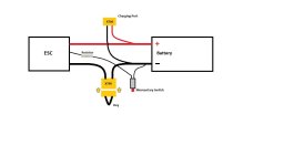
got a qu regarding the anti spark and "key":

does the key and anti-spark have to be through the red wire or could i put it through the black also?
 
BShady said:
does the key and anti-spark have to be through the red wire or could i put it through the black also?
Hey BShady, my key and anti spark actually interrupt the black (negative wire). Until now I thought it makes no difference whether to put it in the positive or negative but I wanted to make sure before answering this so I googled again and came across this:

There's no reason to put the arming switch in the negative wire (unless it's really convenient), but there's one reason I'd put the arming switching in the positive lead.

(1) The arming switch is a potential source of additional resistance.

Any resistance in the negative lead will "float" the "ground" in the esc depending on the current flow in the circuit and is bad electrical practice. In most cases with an opto esc it makes no difference, and with a non-opto esc the ground of your rx will (hopefully) float along with it. But the potential to create ground loops is there, as well as reduce the amplitude of the throttle signal pulse that the esc "sees".

I'm not sure if this will make a difference with the ESC's we're using as mine works flawlessly, just wanted to share this as I was kinda unsure about this too when I started my build.
 
Another reason why I might think this dosent affect us is because the "key" we are useing is the same wire and a connectors which is used to connect the ESC to the battery so this "float" might not happen just like it dosent happen when you don't use a "key". I think the "float" might just apply if your useig a actual switch or breaker which is a relay of some sort.

This is all just from inference, observation and deduction, so i could be wrong.
 
Do you use anything to cover your Charging port or your Xt90 Key when riding in the rain? Or do you not ride in the rain?

Is there any benefit to having a switch on the resistor or just having the resistor connected at all times just as fine?
 
torqueboards said:
Do you use anything to cover your Charging port or your Xt90 Key when riding in the rain? Or do you not ride in the rain?
The XT90 is fine I think as the key seals it but the charging port should be covered up in the long run. It's been pretty dry since I made it but just to be safe when hitting a puddle I'm going to cover it up somehow.
I don't ride in the rain with this setup as it's just a bad idea. I'm sure you've noticed how water turns any surface into something between ice and lubricant with the flywheels. I did ride in the wet before but you just have to be extremely thoughtful in any turn.
torqueboards said:
Is there any benefit to having a switch on the resistor or just having the resistor connected at all times just as fine?
Well, having the anti spark connected at all times means the system is armed all the time so a switch is necessary. It's like the main negative, the thin wire and resistor power up the system and will even move the motors weakly..
 
Back
Top