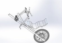
My Velo Pedal Car Prototype

The jackass at Greentime sold me a charger that failed in 30 minutes and said he would replace it when I purchased a few other parts. It wasn't in the box.

Guys got any ideas on how to supply my BMS with the voltage it needs from A/C? 24s 100.8v at full charge

I know a transistor failed because I opened it up after the puff of smoke and it was surrounded by soot.
 
If you really want to try it, you can look up
bad-boy chargers
on google
https://www.google.com/#q=bad-boy+chargers
or here and on DIY Electric Car forums; these do the very minimum to rectify the AC and smooth the resulting DC, and cut down the voltage/current as needed...but they are given that name because they arent' as "safe" to use as a normal charger, and are probably better used only under direct supervision with monitoring devices and a BMS to help protect the pack against failure of the device. ;)

Short of getting the correct charger for it, it'd be safer to get a lab PSU that has adjustable voltage and current limits, that can either directly do the voltage you need, or series that with isolated PSUs that add up to the voltage you need, to let the lab PSU handle the current limiting.
 
nerdalert said:
Guys got any ideas on how to supply my BMS with the voltage it needs from A/C? 24s 100.8v at full charge

Bridge rectifiers are cheap and available for much higher power ratings than you'd think. Trouble is, the peak voltage of "110 volt" AC is about 155 to 170V if you measure it. The nominal rating is the RMS of the sinusoidal wave. So if you rectify AC and feed it to your battery, it'll be seeing 160+ volts 120 times a second.

It would be cool to use a lab power supply with programmable current and voltage limiting, but that's expensive.
 
Bridge rectification with a voltage regulator, resistor and capacitor would fix that. Off the shelf would be preferred
 
nerdalert said:
Bridge rectification with a voltage regulator, resistor and capacitor would fix that. Off the shelf would be preferred

The resistor works great for shedding excess voltage... at one single amp load. But charging amps drop over the course of a charge. As the amps drop, the voltage rises, and your battery gets killed.
 
I'm so caught up in the wholeness of the project that I forgot that I had to supply the BMS with a regulated voltage and current. You're right.

A new charger is on the way from GreenTime. Problem solved. Meanwhile the ride is awesome and really enjoyable. The throttle is too sensitive, to be honest.
 
New charger on the way. The thumb throttle is way too sensitive for the available acceleration. Good thing I have cruise control. GPS said I did 44mph. (true GPS, not tower triangulation)

The electronics box is doing an amazing job at getting rid of the heat from the transistors and voltage regulators on the BMS, 12v step down, and the Motor Controller. It's getting time to build a body.
 
I have been riding my bike to work. It Runs great, Everything is solid.

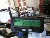
Got the Cycle Analyst V3 in the mail today from Grin/ebikes.ca. Besides the fact that the bottom 1/3 of the LCD does not function, it appears to be a well built piece of electronics.

IMG_20160910_165108.jpg

I was able to make out the Amperage/Wattage during a long high speed run down the street and it was showing 60A 5000w steady. That has to be bogus. I mean, my fuse is only 45A! What gives
 
You may have a discrepancy between the actual resistance and the programmed value of your shunt.
 
I would have figured that one out if it weren't for the illegibility of the screen. :/ Can't read anything. Sure hope they make it all good.

I was under the assumption that if they coordinated with the controller manufacturers to get a 6 pin output they would get them to agree on a set resistance of the shunt. After opening my electronics box on the bike and seeing the shunt, I laughed. Silly me.

I'm new to ebikes. Forgive me.

With my lab power supply and DMM this should be a breeze
 
I sorted the shunt resistor misreporting and Grin/ebikes.ca is sending me a new screen to solder in. I got them to compensate me by sending along a free 6 pin extension and a usb programming cable.

The replacement for the failed charger is here also so it will be tied in and tested. The electronics appear to be 100% sorted minus the lighting, but that comes after the body. I have logged 100 miles so far and it runs great and handles amazing. Rear suspension wouldn't hurt for those potholes I keep hitting in the morning before the sun rises.

Body is coming very soon!
 
Grin/ebikes.ca sent me a replacement screen and I soldered it in and things are back to normal.
 
IMG_20160921_214505.jpg

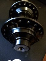
Made the 20mm spindles. in 3 passes I hit .787 from a 7/8 piece of round bar. Slid the hub over the shaft, marked it, then trimmed the end of the shaft for an exact fit with the dust cap of the hub. Then I drilled the hole in the end and tapped them 3/8-16 LH and RH.

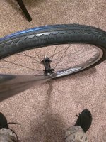
Much easier than trying to make those bastardized bicycle hubs work that are currently on there. Tomorrow I make a jig for welding the spindle to the kingpin tube. Both are stainless. After that I will be making a simple rear suspension because I already bent the rim on a pothole. Not the kind of bent you can true out with spokes. :(
 
IMG_20161004_203952.jpg
IMG_20161004_203939.jpg

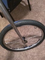
new Kingpins/Spindle Shafts done. 20mm thru axle and 160mm brake mounts

Also modeled it 100% including moving parts

Assem1.JPG

Weight of the spindle shafts was reduced from "heavy" to 3 pounds not including any parts attached
 
Back
Top