Sounds like the new controller is sending many many more pulses per wheel rotation than the old one, so many that the display is overwhelmed and just stops counting them beyond a certain point. But it could be the wrong voltage, or it could be the input is damaged from too high a voltage, etc.
Without knowing what signal the controller you have now is sending, vs what the device requires, both in voltage and frequency, it's going to be tough to fix the problem other than by experimentation.
If you don't have a multimeter or oscilloscope to test the new controller's existing signal, the best you can do is use the setup software for it to set it up to provide the same kind of signal the previous controller did. (same number of pulses per wheel rotation, same voltage)
If you don't know what that is, you can check with Kelly to see what that specific model is designed to output on the specific wire you used for speedometer output. Then use the new controller's setup software to change it's output to match that, on the wire that outputs the right voltage for the display (the same voltage that the Kelly did).
If you cannot change the settings in the new controller, you would have to change them in the display per section 6 of that linked manual, if it will adjust far enough.
If not, then you would have to build an external bit of electronics to convert the signal from the controller to match the needs of the display. This is unlikely to be necessary, but if it is, it's pretty simple electronics, though it would require knowing what is being output vs what is required.
If none of those are possible, then you'd need either a different source for the speedometer signal (externally mounted sensor with magnet on wheel, etc), or a different speedometer display, or a different controller that is compatible with the speedometer display.
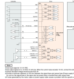
jcovaltine said:This is the only documentation I was able to find on the CT-22 display.
http://www.siaecosys.com/upfile/201908/2019082255434357.pdf
As I mentioned earlier this display was working with a Kelly 72300 controller.
When connecting it to my fardriver 96530. It will display 6 then 18 by barely moving the wheel. But when I spin the wheel up it remains on 18. I’m not sure what signal the fardriver is sending.