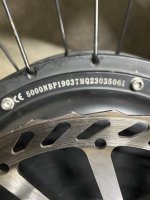
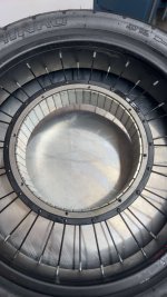
NBP QS205 3T hall sensor issue

branson.cz

100 mW
Joined
Oct 16, 2023
Messages
44
Location
orange county
freshly rebuilt qs205 with a 3t stator and some new magnets. no matter what i try or do both hall sensors give me issues. i can ride it but if i accelerate too fast it cuts off, and on my fardriver app it says hall sensor error. if i use the backup hall sensor it doesn’t work at all. i’ve opened it back up and checked both sensors, checked for cont and ohms. everything checked out and there is no issues. it’s been 4 days and i can’t figure this out
 

Attachments

  • IMG_9722.jpeg
    IMG_9722.jpeg
    1.6 MB · Views: 1
New magnets? Are they identical to the old ones in shape, size, thickness, and strength, and are they installed in alternating polarities?

If they are different from the old ones, the hall signals may not be changing correctly as the controller expects. (or at all)
 
New magnets? Are they identical to the old ones in shape, size, thickness, and strength, and are they installed in alternating polarities?

If they are different from the old ones, the hall signals may not be changing correctly as the controller expects. (or at all)
that actually makes a lot of sense but they are identical, i had to replace 5 that were damaged. they are all the same polarity. maybe side to side spacing in the housing? i put them in the middle of the housing and i’m thinking that maybe they are supposed to be flush with one side and not centered
 

Attachments

  • IMG_4728.jpeg
    IMG_4728.jpeg
    349.4 KB · Views: 4
If the magnets are not installed in alternating polarities (as hubmotors including the QSMotors QS205 do), the motor will not operate correctly, and the hall sensors will not switch as they pass.

If the motor is operating, the magnets must be installed in alternating polarities, or else your controller is able to sense that they are not and drive the motor some other way than the usual to compensate.

Nromally the magnets line up with wherever the stator laminations start and end when the motor is assembled. If yours are placed differently, the hall sensors might not line up either and not read the magnets.


On the QS205 I have here (by QSmotors) it has them centered; if they weren't the side covers wouldn't go on as the lips would hit the magnets closer to that side.
how do i install them in a alternating pattern? like place them how they push each other away
 
Let's say you have the rotor laying flat on a table. The magnets should be isntalled so that the first magnet has a north on the "top", and the next magnet's north is on the "bottom", and so on all the way around, so that you have 23 of them with norths on the side of the rotor facing the table, and 23 of them facing the other way.

They wont' push each other away in this configuration (not nearly as much as if you put them all the same way, anyway), but you'll still have to clamp each one down as you place it so it doesn't move as you place the next one.

The best way is to clamp them all at the same session, so the glue or epoxy, etc used is still workable the entire time you're doing it. That way you can ensure each one is correctly placed and spaced. For this you would need 46 clamps or a nonmetallic fixture that sits in the middle of the rotor leaving only space for the magnets between it and the rotor, so they can't flip around or move

You also have to be sure the spacing between them is as close to identical as possible--there's not much space there, but there can be some. If you have any gaps that are larger than others, the motor will not run perfectly smoothly (you might not notice it if it's small enough, but it will change the way currents have to be driven by the controller, and large gaps anywhere could make it a bit rough).

There's at least one thread here where a custom motor was built and magnets glued down, and at least one more where magnets were replaced on an existing motor, that have some pics of how they did this (unfortunately it was a long time back so I don't have a link; you'd have to find them which is hard with the existing search function, but you can try the old search here:
https://endless-sphere.com/forums-old/search.php
i had no idea i frocked that up, i just placed the magnets how they wanted to go. i’m still curious on how to correctly place them though, is it a pattern?
 
My previous post (which you quoted) already describes how to place them.

Do you have another magnet laying around, preferably a bar shape?

If so, hold it firmly in your hand and move it near but not touching each magnet you have installed, from the side of the rotor. As you go around the circle, it should be pulled to one, then pushed away from the next, pulled to the one after that, etc.

If it is not, then they are not installed correctly.

If it is, they're already installed alternating polarities as they should be.
i think i’m just gonna buy a new motor that sounds too complicated
 
Well, first just check to make sure they are (or aren't) installed correctly. If they are, then the problem lies elsewhere, and we can move on to those possibliities. ;)
 
Well, first just check to make sure they are (or aren't) installed correctly. If they are, then the problem lies elsewhere, and we can move on to those possibliities. ;)


BTW, what was the reason for the magnet replacement, etc?
there was this awful grinding noise when i rode it from the magnets spinning in the housing
 
Well, it's unlikely that the grinding (of the magnet pieces?) caused any damage, since they should only grind against the laminations, and that isn't likely to cause the symptoms you see. At worst they might grind against hall sensor faces, but if they didn't break them they wouldn't cause a problem**** and you said you already tested the sensors to be good (though you don't describe the process used or the detailed results).

****there is a tiny chance that a fragment of broken magnet is stuck in the recess near a hall sensor and is causing it to toggle incorreclty or not at all, but I don't think this is the case based on your symptoms.
if i accelerated too much the stator would rub against the housing, my idea was to take them all out and reglue them. broke 5 magnets in the process and replaced those. i didn’t lay them in any specific orientation, just put them how they wanted to lay down and so they would all attract each other
 
My previous post (which you quoted) already describes how to place them.

Do you have another magnet laying around, preferably a bar shape?

If so, hold it firmly in your hand and move it near but not touching each magnet you have installed, from the side of the rotor. As you go around the circle, it should be pulled to one, then pushed away from the next, pulled to the one after that, etc.

If it is not, then they are not installed correctly.

If it is, they're already installed alternating polarities as they should be.
this makes sense thank you, i’ll just take every other one out and reglue it down. i appreciate your help mr amber wolf
 
I don't know what you mean about "sticks in the middle".

If you do it the way I described, the magnet you are holding can never get near the middle of a rotor magnet, because you will be securely holding it near the ends of the magnets, passing it close enough to feel the pull or push, but that's all.

Then every-other magnet will pull, and the ones between them will push.

BTW, if you only replaced the 5 magnets, not all 46, then the magnets may not be identical unless you purchased them from the company that made the motor and they correctly supplied you with the ones for that motor. Magnets come in different strengths, and different polarizations, so if these don't have the poles in the right places and directions, and aren't the same strength as the originals, things won't work as they used to. (for instance, magnets can be polarized so north is on one large face and south is on the other, or they can have north on one end of the magnet and south on the other, etc.)
i just bought a new motor but thank you for trying to help
 
Back
Top