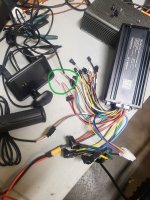
Need help! Any advice is appreciated.

macp444

1 mW
Joined
May 8, 2020
Messages
11
Do I need all the other cables hooked up to power on the display? I'm trouble shooting my ebike(previous controller(Sabvoton) is displaying 30h and can't figure it out. Can't connect either to the app). When I hooked up the power cable, there was a spark. Im guessing that's the voltage loading the capacitors? The display won't turn on. Am I missing something? Plz help. Frustrated with all the money I dumped into this ebike. Tried my 72v battery and 52v and display won't turn on. Voltage is going into the controller.
20240411_202517.jpg
 
Do I need all the other cables hooked up to power on the display? I'm trouble shooting my ebike(previous controller(Sabvoton) is displaying 30h and can't figure it out. Can't connect either to the app). When I hooked up the power cable, there was a spark. Im guessing that's the voltage loading the capacitors? The display won't turn on. Am I missing something? Plz help. Frustrated with all the money I dumped into this ebike. Tried my 72v battery and 52v and display won't turn on. Voltage is going into the controller.
30H is usually communications failure between the display and controller, but you'll need to check your manual to be sure.

If the display won't turn on I don't know how you'd get the 30H error, so you'll need to give details on that.

There are plenty of things that can cause comm error--anything that stops communication:

--display incompatible with controller (hardware or firmware or protocol)
--no power to controller
--insufficient votlage
--no power to ignition of controller
--dead controller
--connection problem in the serial data line(s) between C&D
--electronics failure in the SD line(s)

Not connecting to app:
--no BT module?
--bad BT
--wrong app version
--wrong BT version
--no power to controller
--insufficient votlage
--no power to ignition of controller
--dead controller
--connection problem in the serial data line(s) between C&BT
--electronics failure in the SD line(s)

You'd have to check your manuals for display/controller/etc, but minimum wiring to power system on and get a display is usually
--battery wires to main controller wires
--b+ and ground from controller to display
--serial data tx / rx (or whatever it uses) C to D
--ignition/lock/KSI/whatefver they call it on yours C to D
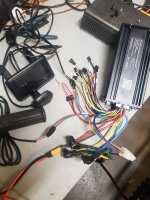
 
This green circle I added...

20240411_202517.jpg


That white connector, with the red wire going in and out, is normally "key lock". It should have full pack voltage for the display. You might want to double check for that. You can make a jumper to close the loop. Then your display should get power.
 
Thanks for the replies. I actually jumped the wire and got the display to turn on but then a hall error popped up. I have a post on reddit(https://www.reddit.com/r/hyperebikes/s/8Q2rUADxl7) talking about all the things I did to get it to work. To get to the point, I cracked open the hub because both controllers I have(one is brand new) have errors. I shot all the wires to the hall sensors. Someone on reddit told me to test the hall sensor by sending 5v through it so I am going to give that a shot.

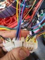
side note: the 2 connectors on the right are controllers and left is the motor. In the sabvoton connector it has the middle pin plugged but the other controller(risun) has a purple wire. The motor has a silver wire in its place which i read is a thermal sensor wire. Would that cause a hall sensor error?
20240412_162954.jpg
 
Have you tested the other set of hall sensors?
 
Have you tested the other set of hall sensors?
This was the key. I thought that the other hall sensors were for the back up plug but it seems that all 6 hall sensors are needed and one of the sensor is dead. It's on the wire that was cut and I repaired. Now to find which hall sensor to order for this QS205
 
I have a QS205 and my hall sensors are SS41 bipolar.

Because they are bipolar, when they are triggered they stay on until the magnetic field changes direction and then switch off.

Looking at your video, one of your hall sensors doesn’t seem to latch on.

Each set on mine is wired to a separate plug.

Mine do seem to blow occasionally for no particular reason on this motor. I suspect it is because the spare set don’t have a pull down resistors to load the outputs, so the outputs are just floating in a high emf environment.

Also the white and transparent wires on my motor are both be connected to one side of a KTY 83 temperature sensor with ground on the other side. The white wire goes to one plug and the transparent wire goes to the other.

In my case the temperature sensor is useless because my controller socket doesn’t have a wire for motor temperature input, so I’m going to replace the temperature sensor in the motor with an NTC 10K and connect the white wire to one side and transparent wire to the other and monitor motor temperature using a standard temperature meter.

I have a Risunmotor version of a 72100 Sabvoton controller. It isn’t as versatile as some other so called Sabvotons because it has a limited amount of wiring. For example, mine doesn’t have high brake connectors and no 3 speed switch connector, as well as no motor temperature input.
 
Last edited:
This was the key. I thought that the other hall sensors were for the back up plug but it seems that all 6 hall sensors are needed and one of the sensor is dead. It's on the wire that was cut and I repaired. Now to find which hall sensor to order for this QS205
Only three are needed, but normally they all would be from the same set, and normally you only hook up one set at a time (I haven't had a controller that had a place to connect more than one set at a time; if you parallel them the motor may not run correctly especially if one of the sensors is not working right).
 
Only three are needed, but normally they all would be from the same set, and normally you only hook up one set at a time (I haven't had a controller that had a place to connect more than one set at a time; if you parallel them the motor may not run correctly especially if one of the sensors is not

Only three are needed, but normally they all would be from the same set, and normally you only hook up one set at a time (I haven't had a controller that had a place to connect more than one set at a time; if you parallel them the motor may not run correctly especially if one of the sensors is not working right).
Well I am still getting a hall sensor error after replacing the dead hall. The motor doesnt turn over easily which I've found other fourms saying the phase wires are touching but I get continuity between all phase wires. Not sure where to go from here. Qs205 motor w/ sabvoton and risun controller.
 
Well I am still getting a hall sensor error after replacing the dead hall. The motor doesnt turn over easily which I've found other fourms saying the phase wires are touching but I get continuity between all phase wires.
Yes, because they are all connected at the center (Wye connection). If you want to test resistance between phases you either have to disconnect that, or use a meter that can distinguish between the very low resistance of the motor coils and an actual short circuit, such as the DE5000


Is it only hard to turn when connected to the controller, or even when not plugged into anything? The former means the controller probably has blown FETs, the latter means a motor issue (but this usually causes blown FETs, so you may have a damaged controller as well in this case).

Motor problems are usually a failure inside the cable itself, at the exit from the axle, almost always from crash damage or from improper mounting of the motor to the frame that allows the axle to spin, or that crushes or pinches the wiring against hte frame. All of these cause essentially the same damage--it damages the insulation between wires, which can allow any of these damaged wires to short together, whcih means phases can short to halls and blow up the controller and the halls, so even after the short is removed the controller can't read halls anymore and will always have an error, if this has happened.


What was the specific situation that happened before your failures / problems began? More details are better, as they will help us help you resolve the problems and get your stuff working again.

We can't know anything you don't tell us, so we can only guess and make assumptions, any or all of which could be wrong and lead you down a wrong path.
 
It initially died on me and I found a chaffed wire coming out of the axel. The wire went to the 2nd set of hall sensors on the 2nd connector from my qs205 motor. I repaired the wire and the hall sensor it went to because it was showing dead(no lights on my tester). I am still getting an error on both of my controllers(one of which is brand new) and I've tried multiple batteries so it leads me to believe the motor is the issue. I have shot all the wires to the controller and all shot good. When I shoot continuity between the phase wires, they all beep so that might explain why there is binding on my wheel and it won't spin freely. There is a lot of resistance but I can get it to turn. The motor and controllers are all fairly new just the one wire broke. Below is my hall sensor tests after the repaired hall sensor on the 2nd set.

1st set of hall sensors test

2nd set of hall sensors test
 
Back
Top