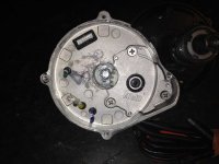
New Bafang Crank-Drives

Lightning_boy said:
I apologise if this has been dealt with in the previous 33 pages of postings; I have read them all but I simply can't remember: has anyone used the BBS-01 or BBS-02 in a single speed set up, and if so, what's it like?
Seems a little pointless to use this with a single speed. You would be better served with a hub motor, and most hub motor kits will cost less than the Mid Drive.
You COULD upgrade your single speed to an internal geared hub. That would be a nice set-up (More durable than a derailleur set-up) , but of course an IGH hub would cost $$$.
 
this is not pointless, it should look the same from the inside. Just the bafangs gears are made of steel :shock: so much better quality, they will take at least double of what the bosch will do

file.php
 
still, the tapered shaft of the bafang is more common, bosch got some market pressure :D that is really good! Maybe we see some multi speed middrive next year. Really, this is all we are waiting for, isn't it????

BUT: how many poles has the rotor?? Did i really miss that??? What about a Wiki Entry?? Simply add it here... it really isn't hard work!?!
http://endless-sphere.com/w/index.php/EBike_Motors_Middrive
 
spinningmagnets said:
Wonderful pics, Kepler...thanks for posting that. Could you do me a huge favor? I'd really appreciate it if you measured the width and length of the stator teeth, and the ID of the stator, plus the dimensions of the bearing that sits down in the hole?

Stator tooth width 8.2mm
Stator tooth length 29.77mm
Stator ID 59.9mm
Stator OD 98mm

Bearing is a little harder to get an accurate measure on but it looks to be 24mm x 8mm and 8mm deep
 
teslanv said:
Lightning_boy said:
I apologise if this has been dealt with in the previous 33 pages of postings; I have read them all but I simply can't remember: has anyone used the BBS-01 or BBS-02 in a single speed set up, and if so, what's it like?
Seems a little pointless to use this with a single speed. You would be better served with a hub motor, and most hub motor kits will cost less than the Mid Drive.
You COULD upgrade your single speed to an internal geared hub. That would be a nice set-up (More durable than a derailleur set-up) , but of course an IGH hub would cost $$$.
Or you could go with the All-in-one solution of the Copenhagen Wheel. - those are up for pre-order now.

Isn't rear spacing an issue with a single speed, which I assume is 120mm? As best I can tell most hub motors are too wide, as are the better IGHs, unless the rear is spread by 15mm. I just wondered whether the BBS mid-drives have enough torque to get a single speed moving easily if it is geared for, say, 25 mph at a decent cadence. With a thicker chain and permanently straight chain line the drive train should prove to be more robust. Add the stealthy mounting location and quiet running and you'd have yourself a simple, elegant and quick bike (in principle at least).
 
BBS-02 has plenty of torque and no problems starting even on the highest gear. Acceleration is gentle but similar to a small geared hub. Although having a range of gears is one of the main points of mid drive, I can see the drive working well even on single speeder with a say 15 tooth freewheel.

A good option if the bike has 120mm dropouts that is for sure.
 
Using it as a single speed would have an unsprung weight advantage on rear suspension bikes, be more centralised weight distribution, probably better wire routing, and you could tune the ratio with sprockets instead of wheel diameter.
 
Why do single speed though. It's going to cost you more than a hub motor, and you are also taking a small motor, reducing it's speed once, reducing it again, reducing maybe even a third time, and then increasing it's speed. In each stage, you have power robbing friction.

This is okay if you have multiple gears to play with. Otherwise, you are wasting energy and paying for a much more complex setup than you need.

There are hub motors out there designed for 120mm dropouts. You could get a MAC motor designed for such this task, if you ask paul over at em3ev. I think that is the largest hub motor you could ever fit into a 120mm drop though.
 
After having a good look at the motor section of this drive, I was keen to have a closer look at the rest of the drive. Avigo gave the nod for me to strip his drive down for a closer look 8)

So firstly the rotor and primary helical gear. Looks to have 16 poles. I like the fact that the primary gear is steel as opposed to the Bosch which is a type of plastic.
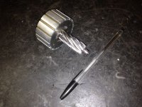
IMG_2897.jpg

The secondary gear bearing housing

IMG_2898.jpg

The secondary gear housing removed revealing good sized sealed support bearing. You can also see the locking collars that hold the bottom bracket shaft in the housing

View attachment 11

The helically cut secondary gear is nice and wide to handle plenty of load and has an internal sprag or one way bearing press fitted inside. This allows the secondary reduction to free wheel under certain operating conditions.
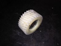
IMG_2909.jpg

This shot shows the 2 support bearings for the primary and secondary gears
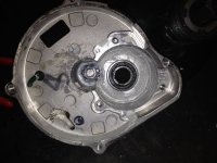
IMG_2915.jpg

Final drive gears exposed. Both these gear are steel but helically cut to keep noise down. You can also see PAS sensor plug and motor phase cables
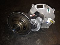
IMG_2907.jpg

Controller is fully potted. Great for weather proofing. Not so good for repairs.
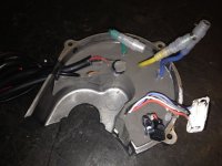
IMG_2906.jpg

This shot shows the final gear removed together with the bottom bracket shaft and associated bearing. The PAS sensor is also visible once the final gear is removed. The locking collars and one of the thrust bearings are also shown.
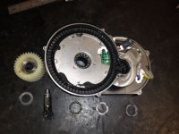
IMG_2922.jpg

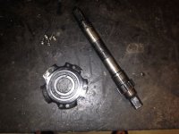
The shaft and final gear comes out as an assembly after removing 2 locking collars on the non drive end of the bottom bracket shaft. The 2 bearing surfaces for the one way bearings can also be seen on the shaft.
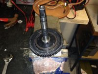
IMG_2916.jpg

A magnetic ring is keyed to the shaft for PAS sensing. This is held in place with a "C" clip
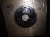
IMG_2924.jpg

With the PAS sensor ring removed, the rear bearing support for the bottom bracket shaft is exposed.
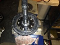
IMG_2926.jpg

Once removed, the main free wheel can be seen. The free wheel uses a 3 paw system for drive engagement.
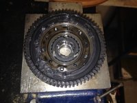
IMG_2927.jpg

Final 2 shots show the bottom bracket shaft and rear bearing housing.
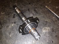
IMG_2930.jpg

IMG_2931.jpg

The bottom bracket shaft, although square taper should be nice and strong considering the amount of bearing support it has. On the free wheel section, it has sizable bearings on both sides with the outer bearing being nice and close to the start of the square taper. The shaft is then supported across its length with 2 sprag or one way bearings. Thrust bearings are fitted at both ends of the shaft to control lateral movement. As the shaft has the one way bearings driving directly against it, we can presume the shaft is case hardened and should resist any bending from our more adventurous riders.

So the drive has a three different areas where it can free wheel from. The chain ring, the primary shaft, and the secondary shaft.

All gears are helical cut and look like they should handle a fair bit of abuse.

All in all, this is a nicely engineered piece of kit.
 
Wonderful pics! Thanks. There is a European E-bike forum that has had their hands on the 250W units a year before the 750W became available to us. On the disc that has the PAS sensor magnets, there are pair-sets at two places, 180-degrees apart. I'm told they use pairs because the north and south magnetic faces are paired next to each other, and this tells the chip which direction the BB is spinning. So speed calculation pulses take 180-degrees of crank rotation, and comparing two pulses (to sense if you are speeding up or slowing down) takes 360-degrees of pedaling.

For the cost of four more tiny magnets, they could have removed half of the lag in the PAS system in applying power, and also when reducing power.

edit: see post by Kepler two posts below for more accurate info on the PAS response...

file.php
 
Great photo series, Kepler :) What do you see as the likely failure mode for hot rodding these units?
 
I think mechanically, the unit is very sound. IMO, motor and controller failures will be the big issue when people start to hotrod these things. I am normally a big fan of over volting however over volting makes little sense to me with mid drives due to the direct effect on cadence. I see no point in spinning the cranks quicker than your legs can comfortably handle.
 
spinningmagnets said:
Wonderful pics! Thanks. There is a European E-bike forum that has had their hands on the 250W units a year before the 750W became available to us. On the disc that has the PAS sensor magnets, there are pair-sets at two places, 180-degrees apart. I'm told they use pairs because the north and south magnetic faces are paired next to each other, and this tells the chip which direction the BB is spinning. So speed calculation pulses take 180-degrees of crank rotation, and comparing two pulses (to sense if you are speeding up or slowing down) takes 360-degrees of pedaling.

For the cost of four more tiny magnets, they could have removed half of the lag in the PAS system in applying power, and also when reducing power.

As far lag goes on the is drive, I think it actually one of the best I have used. 1/4 turn response on both start and stop. Also a nice ramp on startup Perhaps they have improved it since first units released into Europe. :)
 
Thanks for photos Kepler! If I ever need to disassemble the motor, these photos help a lot!
I would like to know, is there a cup and cone bearing on the BB shaft that should have certain tightness?
Call me over sensitive but I can actually feel some play in cranks. When I twist the throttle, cranks twitch a bit, and when I let go of throttle they twitch back. Perhaps the whole motor is moving if the motor BB-assembly locksrings are loose, or the final gear axle is moving inside the motor. I can also feel the final gear fibrate more when the right side pedal points forward a bit downwards. Should I be worried?
KAI
 
No good - I've buckled - I've ordered a 48v500w unit :)

Going to use with with a 15s lipo pack - we'll see what the rpms are like and have a think about the lvc thing.
 
How waterproof are these units likely to be? If I planned on rain riding, what extra sealing should I be doing?

Also, Kepler (or others): this would be my first build, and I'm a little wary of wiring batteries correctly. Is it easy to hook up little turnigy cells in a handlebar bag, or am I better off with just getting the downtube battery direct from lectric cycles?
 
Waterproof grade: IP65 ref:http://www.ebike-discount.com/onlin...RAL+MOTOR+DRIVE+SYSTEM+-BDS01-+Feb+182013.pdf

You can read about what the numbers mean here: http://en.wikipedia.org/wiki/IP_Code

The following question is: Can you trust what the manual says?

edit: According to Keplers pictures it does not look as if there are any O-ring seals (please correct me if I'm wrong), but there seems to be some residue from some form of liquid sealant. If the faces of the different covers are machined somewhat straight then you could always seal it yourself with some extra sealant. The controller is totally potted which is good from a water ingress point of view.
 
Kai said:
Thanks for photos Kepler! If I ever need to disassemble the motor, these photos help a lot!
I would like to know, is there a cup and cone bearing on the BB shaft that should have certain tightness?
Call me over sensitive but I can actually feel some play in cranks. When I twist the throttle, cranks twitch a bit, and when I let go of throttle they twitch back. Perhaps the whole motor is moving if the motor BB-assembly locksrings are loose, or the final gear axle is moving inside the motor. I can also feel the final gear fibrate more when the right side pedal points forward a bit downwards. Should I be worried?
KAI

There are thrust bearings on each end of the bottom bracket assembly. The locking rings on the non drive side of the bottom bracket set the tension on the thrust bearings.

There are 2 locking rings so you need to remove the first ring. It won't be tight so tap with a small drift against its slots will move it. There is then a weather seal to remove. Now you have access to the main adjusting locking ring. Just nip this up until all lateral play in the shaft is removed the shaft still spins nice and smoothly. Re fit the weather seal and second locking ring. Again, light nip up is all that is required otherwise you will damage the weather seal. The weather seal acts as a locking washer also.

That twitch you are talking about my be coming from the controller. I find on low power settings, i do get a bit of shudder or twitch when first taking off.

With two the Sprag bearings working directly against the shaft, it would be very unlikely to have any up and down movement, only lateral movement if the thrust bearing tension is too loose.
 
amigafan2003 said:
No good - I've buckled - I've ordered a 48v500w unit :)

Going to use with with a 15s lipo pack - we'll see what the rpms are like and have a think about the lvc thing.

15S, seriously? Seems like a lot of stress on the motor and ESC for very little advantage. The drive does 50kph on an 11 tooth gear and 12S. Your call, but personally I would stick with the voltage the drive has been designed for. :)
 
bose said:
Waterproof grade: IP65 ref:http://www.ebike-discount.com/onlin...RAL+MOTOR+DRIVE+SYSTEM+-BDS01-+Feb+182013.pdf

You can read about what the numbers mean here: http://en.wikipedia.org/wiki/IP_Code

The following question is: Can you trust what the manual says?

edit: According to Keplers pictures it does not look as if there are any O-ring seals (please correct me if I'm wrong), but there seems to be some residue from some form of liquid sealant. If the faces of the different covers are machined somewhat straight then you could always seal it yourself with some extra sealant. The controller is totally potted which is good from a water ingress point of view.

A lot of thought has gone into the way this drive is sealed. There are O rings on the main mating surfaces and all electrical cabling is sealed where it penetrates the casing and main electronics fully potted. The plugs on the external loom are a very nice design and snap together with a rubberised seal face covering the connection.

Best sealed drive I have come across to date and would confidently ride in the rain if i had to. I wash my bike with a hose all over without any problems at all.


There is no residue from liquid sealant in the drive, just white grease used for the plastic gear lube.
 
Kepler said:
Best sealed drive I have come across to date and would confidently ride in the rain if i had to. I wash my bike with a hose all over without any problems at all.
Speaking of rain, hoses, and weather, how do you protect your battery on a rainy day?
 
dshack said:
How waterproof are these units likely to be? If I planned on rain riding, what extra sealing should I be doing?

Also, Kepler (or others): this would be my first build, and I'm a little wary of wiring batteries correctly. Is it easy to hook up little turnigy cells in a handlebar bag, or am I better off with just getting the downtube battery direct from lectric cycles?

As newbie, go with the lectric cycles battery or the new one from EM3ev. http://em3ev.com/store/index.php?route=product/product&product_id=161
 
Rollodo said:
Kepler said:
Best sealed drive I have come across to date and would confidently ride in the rain if i had to. I wash my bike with a hose all over without any problems at all.
Speaking of rain, hoses, and weather, how do you protect your battery on a rainy day?

No problems, those Topeak bags come with a yellow rain cover that protects the contents nicely from getting wet. :)
 
Back
Top