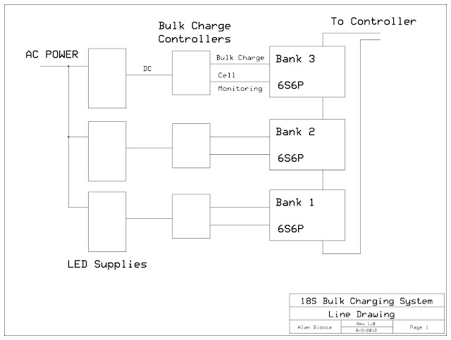
One KiloWatt 18S Bulk Charger

Alan B said:
It takes a "basic" charger and makes it into an "advanced" or "deluxe" charger.

I would add to that... It also makes it MUCH SAFER to charge and after charge too, since it can shut the charge off AC/DC "both sides" completely too. [<=Edit: Does not cut the AC side off, so that would need to be done another way if required.]

I believe it will cut or switch the AC power off too, so no power is left on the PS Charger keeping it "hot on". [<=Edit: Does not cut the AC side off, so that would need to be done another way if required.]

This design will also have "the effect" of preventing battery voltage/current from reversing and going back into the PS Charger from the battery too.

Please correct me where I'm mistaken... [Edit: See Next Post from Alan.] Thanks. :D

Here are some comments from Doctorbass about protecting your PS Charger...

Doctorbass said:
miuan said:
ALWAYS operate the charger with an output fuse!


I would rather recommand using two schottky diode! it will really protect against reverse polarity.

you install one in parallel with the charger output ( in the non conducting way) than after that you connect one fuse in serie and than one schotkyy diode in serie on.

by that way you will protect against EVERYTHING, :

-Higher voltage battery than charger output
- reverse polarity
- battery being drained by the charger when unpowered


Cost 5-10$ and 15 minute of work.

Will save you 200-300$ and few hours of frustrations!

Doc
 
At this moment it doesn't cut off the AC. For one thing the AC is powering the charge controller. It's a possibility but there are some issues. But it does cut off the DC using IRF4110 FETs or similar. So there is no output current, aside from FET leakage, and that's very very small.

We might want the software to charge the pack every few days just to keep it topped up - a timer could be programmed for that.

These LED supplies are designed to be very efficient even when the load is off, so very little power is consumed when they are on with no load.

How important is it to turn off the AC? If we do that the board will have to either go off, or be powered from the bike battery.

Another thing this controller can do is avoid the big spark when plugging in the battery to the supply. It waits a few seconds before starting up the charge cycle. It won't start charging until it sees the battery on there for a few seconds.

If the battery is backwards it won't come on. If the battery is way low it won't come on. Safety first.
 
motomech said:
From the MeanWell spec page;

"B" Suffix: IP67 rated. Constant current level adjustable through output cable with 1~10Vdc or PWM signal or resistance."

Could this feature be used to, if not achieve complete shut-off, reduce current flow to Zero or near zero?

Woah, this makes me want to subscribe. I hope someone has explored this.


I don't know much about digital potentiometers, but for a while I have been toying with [in my head] how relatively easy it would be to have a little AVR board that controls a digital pot and measures output voltage and current, and adjusts the digital pot to control the output voltage until target voltage. The digital pot would replace the existing potentiometer adjustment (or work in conjunction).
 
Another option is to use a DAC chip instead of a digital pot chip. Digital to Analog converters are often more precise and more suitable to power supply control applications, but it depends on the power supply design. But really if you are going to go that far then just have the micro PWM the power supply switching devices and forget analog controls. Measure voltage and current and adjust output duty cycle to control things. That's how the RC chargers work. Just build a bigger version.

But in the case of the LED power supplies, they are already voltage and current regulated. So you don't need to get involved in that. Unless you want to make a charger that can adjust to different cell counts. If you decide to do that just be aware that software errors in a system like that can cause fires by overcharging batteries.

In the case of using a preset regulated supply the only decisions to make are when to start and stop charging. Even if made incorrectly they are not going to risk a fire. So the system is a bit simpler and safer. All the dangerous stuff and hard stuff like high voltage, isolation and power factor correction is taken care of by the manufacturer. All we have to deal with is DC, mostly less than 50 volts, possibly up to 100 volts.

There are other threads here on ES and elsewhere about DIY and bad boy chargers that get into these discussions about "direct control" of a supply. I will probably get around to that later on, perhaps with a variant of this board, but for now I'm focussing on this useful building block.
 
Made a little progress. Sized the tantalum bypass capacitor, upgraded to a resistor array (saved having to place 5 parts and gained some space), improved the PCB layout in many places, added component numbering, etc.

Reviewing the design, I am reminded that this is aimed at 6S which is less than 30 volts. My plan for 18S is to use three power supplies, and three of these controllers. Each one will independently monitor and control the charge on a 6S "bank" of the battery, and it will work on a 6S, 12S or an 18S ebike battery. In the case of the 12S ebike one section will not be active. But I can use the same plugs for easy no-risk hookup.

I was hoping to handle higher voltages but there is not sufficient space on the board, and so many issues are raised by this it does not appear practical to meet higher voltage requirements as well as the other project requirements.

There are several areas that have problems as the voltage is raised. One is the voltage regulator. A more complex scheme is needed to go above 30 volts.

The DC switch can handle higher voltage, up to about 100 volts due to the IRF4110 devices there. So no problem with that.

The power supply and battery ADCs can be rescaled for higher voltage by changing resistors. There may not be sufficient clearance on the PC board to meet minimum spacing requirements.

The cell monitors are also a problem. This would not work at more than 6S anyway, and at higher voltage would get more complicated.

This design looks excellent for 6S, and would work fine on 4S or 5S. To go beyond that simply use more than one of them. :)
 
deVries said:
I humbly suggest 8s for A123 29.2v @ 3.65v & 8s Celllogs. :D

That might work. Leave off my 6S monitoring parts from the PC board and use a Celllog instead. I'm out of space and out of ADCs to do 8S on this board. Take the output of the Celllog and bring it in on one of the then unused ADC pins and adjust the software to read it as a binary. Should be fairly straightforward to do. :)

I don't think the 24V Meanwell supply will adjust that far though. Perhaps they have another model that will reach that voltage.

I'm aiming for 25.something volts.
 
OK on the supply, they make quite a few voltage ranges.

One comment I've heard about celllogs is that occasionally they don't work right, so they might fail to provide protection against cell overcharge. Since this is a backup mechanism it would only be a problem if it happened to fail at the same time a cell happened to overcharge, so a small risk.

One other safety I wonder about is a "rate of current decay" detection. Once the system is charging in the "constant voltage" region of the charge cycle the current should be dropping off. If the current goes up, or fails to drop off after awhile it might be a condition to terminate the charge cycle.

Other charge terminating conditions are:

* charge current drops below minimum current for period of time (minimum current recommendations range from 3 to 10 percent of pack capacity)(time of say 3 seconds, many readings of current verification)
* cell voltage too high
* pack voltage too high
* total charge time exceeded
* total amp hour charge energy exceeded (pack capacity plus x percent)
* pack or environment temperature in safe charging range


Other progress

I made a little more progress on the BOM (bill of materials). Still lots to go on that, much of that info is embedded in the pc cad file.
 
Alan B said:
OK on the supply, they make quite a few voltage ranges.

For 8s LiPo they have: HLG-320H-36 ... 32v-39v.

My understanding of the Celllog problems is mainly w/on-off "boot-up" or "screen scrambles", but what other common error conditions have you found out or heard about?
 
Alan B said:
teklektik said:
From your description, it sounds as if Fechter's Mini Meanwell Limiter V.3 can provide the charge-limiting and termination you require along with optional per-cell HVC by CellLog, etc. Have you determined that it is incompatible or is the integrated Ah meter a critical part of the desired solution?

The Fechter Mini Meanwell Limiter is not needed with these LED supplies, they already do that part - current limit and constant voltage. I don't see a shutoff there, it just keeps at a constant voltage as the current drops down.
The termination feature is perhaps better explained later in the development rather than the sales thread for this board - so, a minor clarification (not to detract from your efforts here :D ) - the Fechter board affords two features, each with an associated LED charge-mode indicator:
  1. a means to adjust the current for chargers that are not normally adjustable to the desired value (or for those who don't feel comfortable tinkering inside a supply to get the limiting they wish),
  2. an external input for open collector trigger as with a single CellLog or bank of CellLogs with optoisolators. This terminates the charge by tricking the charger 'voltage sense' line so the charger output voltage drops to a level inadequate to further charge the pack. This affords an effective shutoff without using FETs to sever the main power - the charger itself handles the shutdown so there are no high power components on the board itself.
The Fechter v.3 mini board is a basic DIY component that comes into its own when augmented with CellLogs or other monitoring boards. When used with CellLogs, the board terminates charge on any CellLog alarm: individual cell LVC/HVC and/or pack LVC/HVC with the configurable CellLog time-to-trip delays. Although some folks bulk charge with series chargers, a single board on one charger is typically sufficient to handle these higher voltage situations.

I think you have an interesting project afoot here - just want to call out some of the features of this previous undertaking so that its features and use cases might be more well understood and, if appropriate, perhaps built upon rather than starting from scratch.

Specifically - acknowledging that you are using the FET instead of voltage-sense approach to termination, it might be nice if you could operate at higher voltages so that only a single unit would be required for bulk charge situations. Some scheme equivalent to the Fechter select-a-zener approach might be used to configure the operating voltage at build time (in concert with any resistive divider mods for ADC scaling). Here you might also provide a second optional 'glue' PCB with nothing but optoisolators to afford a means to tie multiple CellLogs to your unit (just optos - a means only to minimize pt to pt wiring).

It's a little unclear what you have in mind for the final deliverable. If you are going to have the boards fabbed, then SMD is fine. But if you want to just sell boards, then a larger board with through-hole components would be a much more tractable form for most ES members than requiring SMD fabrication skills. Since this is a charge-time device, size is not much of a consideration and the ease of construction would likely out weigh the increase in cost for the bigger board.

Again, an interesting project - just throwing out a few thoughts :)
 
Thanks for the feedback and comments.

It is unclear where exactly this project will lead. That is a bit intentional on my part, I don't want to generate unfulfilled expectations.

This unit is specifically being designed for these LED power supplies and 6S Lipo. It can be used for other purposes, or it can also be the starting point for some other design variations. Anyone want to make a variation?

To work with these LED power supplies the high current switching is required.

I like your suggestion of a second board to make it higher voltage and celllog compatible. Another possibility would be to strip off the cell level monitoring from this board and make a variant that had a high voltage pre-regulator and celllog optical inputs. Or even strip off the FET switching and provide an output for the Fetchter board.

Another thought is to make a second board that would have high voltage pre-regulation and lots more cell inputs. Take it from 6S straight to 24S or more.

But first I need to finish this 6S Lipo version.

In terms of through-hole construction, I was planning that at the start, but it didn't work out. I think we need to find folks that can build SMT stuff for us. Folks who want to do their own SMT can do so easily enough, but not many folks seem interested in this. It can be done with fine tip soldering pencils or mug warmers and hot air embossing tools for less than $50, or a pretty high end workstation setup from china for $600. So we need to find solutions for those that don't want to roll their own.

I don't know what all the celllog failure modes are. Jeremy indicated something about them getting stuck occasionally. Perhaps he'll comment further on that.
 
Alan B said:
This unit is specifically being designed for these LED power supplies and 6S Lipo. It can be used for other purposes, or it can also be the starting point for some other design variations. Anyone want to make a variation?

My 2c-

I would install this in my charging system if it were set up to run at high voltage directly, I would probably get rid of the cell-by-cell monitoring and use Methods detector boards instead (or move the cell-by-cell monitoring to a daughterboard? Expandable? Optoisolated interface? beware feature creep! Shunt balancing? Lol.) I don't trust cell-logs for anything permanent or critical.-

The most valuable aspects of this design to me are the data display and Ah tracking, which could be set up to be a bit more handy and charging application-specific than just a CA, and the ability to put a little extra logic in the charge cut-off, and some safety rules, for just a little added functionality over Methods HVC breaker board.

In all honesty though, a CA for monitoring and Methods system for safety is pretty much an acceptable system to me, this system would have some extra nice-to-have features, but not really critical.

Hm, that reads pretty critical. I don't want to discourage you from continuing to build this, and I think it will be sweet! At the end of the day, YOU should build what YOU want :)
 
I like the channel expansion via daughterboard theme.

One thought is to stack three of these boards but only put the LCD and pushbuttons on the top board. Do an optical interconnect between the boards of some kind. Then it would do 18S with only one display and user interface. I have considered this before, but not very thoroughly. The biggest problem is the optically isolated interconnect needed. This solves the high voltage problem since each board is powered by one 25V supply, at least for that particular configuration.

Having these discussions on the forum is very useful. I can't take every suggestion or request but thinking about them often generates other ideas.

One constraint is to finish this soon. Need to get it done. Better is the enemy of Good Enuf.
 
Alan B said:
Better is the enemy of Good Enuf.

indeed how few appreciate this point :)

Anyway I would chime in and vote to make the board compatible for higher voltage operation and delegate the cell monitoring to some other module of the system. If only 6s then there seems less reason to be bulk charging via a power supply and not just with some cheapo RC balance charger. Now if it were good for..12s or maybe even 24s with same layout and just some component swaps. That's were bulk charging comes into its own... perhaps with such long strings its also where cell level monitoring is important too ... agh.

One other idea... even if delegating the cell level monitoring to another module you could have multiple inputs (one for each pack.. so your LCD could flag which pack had the high cell, if not to the exact cell)..

Also why not go the next step and chuck in support for 1 wire temp sensors (DS18B20).. you could monitor temperature at the pack level as well. You can string them all off one I/o anyway.

Dean
 
Welcome to Endless Sphere, Dean.

Great suggestions. I've used those temperature sensors. Very nice devices. This morning I was thinking about adding temperature range to the charge conditions list to avoid charging outside the safe temperature range. Then I fired up the laptop and your message is here. Amazing!

Here's what I'm planning to do on my 18S setup. It could be expanded to 24S easily, or 30S. One PC board design does it all. Keeping in mind that each separate PC board design costs a couple hundred bucks to prototype, or more, I'm trying to keep costs, effort and project duration down at this stage. Each board sees only 25 volts. No high voltage regulation needed. Buy three power supplies. Build three Controllers. Want 24S? Do four of each. The wiring plant is also suitable for RC chargers for those balancing events. :)

bulkchgcont%2520sys.jpg
 
Alan B said:
Welcome to Endless Sphere, Dean.
Hi Alan, thanks. I kind of forgot that is was so obvious... "1 post" :) I have been lurking around on and off here for a few years, yours and many other names familiar in all these electronics development threads :)

re your point on high voltage regulation, I did think of it also after my post that it's not necessarily so straight forward to adapt for high voltage (indeed much more than just trivial component swap) though I suppose you could use a separate LV supply. My desire was just for a simple add on upgrade for something like one of those BMSBattery chargers.

Anyway I see that your block wise approach while perhaps more components and interconnects for a medium size battery stack, is much more scalable as you go beyond that and in which case is worth to maintain the cell level monitoring capability as well.

As you were :)

Dean
 
dm9876 said:
re your point on high voltage regulation, I did think of it also in hindsight that it's not necessarily so straight forward to adapt for high voltage (indeed more than just trivial component swap) though I suppose you could use a separate LV supply. My desire was just for a simple add on upgrade for something like one of those BMSBattery chargers.

Anyway I see that your block wise approach while perhaps more components and interconnects for a medium size battery stack, is much more scalable as you go beyond that.

Dean

Yes, it would be easy to add a pre-regulator to use this with a BMSBattery charger, and either skip the cell monitoring or use celllogs or an external circuit to do it. Once we get something working it may develop in other directions. Perhaps some other folks will develop add-ons, or variants of this. I feel the need to get something working soon, or I will run out of time and enthusiasm for it.

I have a couple of the BMSBattery chargers so I might want to go in that direction at some point. I never know if they are going to work (so far one has worked fine, the other I haven't used) or blow up, based on what I read about others experiences. With no display it is hard to know what they're doing. It would be nice to have a display and safety monitor on them. If we build this controller board but leave off the cell monitoring components, and make a pre-regulator to drop the supply voltage down, or use a small wall-wart to power this controller, it should work to provide the other functions for the bulk charger.

We still need to identify a good way to get hardware built beyond some prototypes. Perhaps someone who builds hardware would be interested in pursuing that, such as Methods.
 
more ideas.... can't help it once I start thinking.

I can't recall if you mentioned and I couldn't see from your layout which uC you were going for, but with the comments on Arduino compatible and headers for USB / serial converters, I presume the standard atmega328 from an Arduino UNO?

Have you considered using ATMEGA32U4 ? lost more I/O's USB interface built in (some consideration perhaps needed for isolation depending on how you might want to use that)

There is the Arduino Leonardo that uses it so full Arduino compatible

maybe it's too small for easy construction, but you could also look at using the "teensy"

http://www.pjrc.com/teensy/

which is pre assembled and pre programmed with bootloader (not the Leonardo one but is compatible with Arduino) on a board with standard 0.1" pitch connectors. for $16

that could simplify the DIY construction for many and having the uC component also modular increases the "hackability" of the design for later

Dean
 
dm9876 said:
... you could also look at using the "teensy"

http://www.pjrc.com/teensy/

which is pre assembled and pre programmed with bootloader (not the Leonardo one but is compatible with Arduino) on a board with standard 0.1" pitch connectors. for $16

that could simplify the DIY construction for many and having the uC component also modular increases the "hackability" of the design for later

Dean
I had been envisioning the same uproc-module strategy for through-hole construction - should have included links - my bad - (ebay 'arduino nano') or (ebay 'meduino nano')...
 
The Nano's don't help this design as much as the Teensy does. The ATMega 328 is just a bit shy of what is needed in the ADC department. If we want to do 8S, plus the current and voltages we need 11 ADCs where the 328 has 8 and the Teensy with U4 processor has 11 (12 actually but one is pre-empted to an LED). Even at 6S we need 9 ADCs which caused me to add a MUX chip, so this saves that chip too.

So here is what it might look like with a Teensy:

bulkchgcont-0f0.jpg


There may not be enough room for 8S differential amplifiers.

I searched Digikey for through-hole differential amps and did not find anything reasonable. There were a couple but they were expensive and not small enough. There is not much room either.

The current sensor is also only available in SMT.

The cost goes up about ten to fifteen dollars, but risk is reduced.

The USB interface is nice, however it is not isolated so presents some risks. The serial port before was not isolated so this is similar.

Another thing I like about the U4 is that it has a temperature sensor which gives environmental temperature. This is not battery temperature but it is useful.
 
Hi Fred.

Schematic is not presentable at this time. It is mostly in separate index card notes or in my head. I was entering it but now sidetracked with the Tiny. In order to give freedom to the PC layout I let the schematic float a bit. Many things have flexibility with where they can go, so it makes the PC layout easier and cleaner to let layout drive things.

Did you have something specific you were wondering about?
 
Back
Top