One KiloWatt 18S Bulk Charger

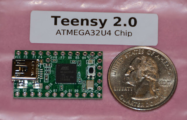
The USB interface is nice, however it is not isolated so presents some risks. The serial port before was not isolated so this is similar.

Does it save any room to use a mini-usb port?

Also, what is the cost/problem with just using the next size up pcb to give you more room to fit everything through hole? Do some shops offer different "sizing" alternatives that might make it more feasible vs others?
 
Alan B said:
Hi Fred.

Schematic is not presentable at this time.

Did you have something specific you were wondering about?

I am interested in the current measurement and how the analog voltage detection is performed with the resistor array.
 
The USB port is on the Teensy board, and it is a mini USB. So no space is used on the main board.

The differential amplifiers in through hole were over five bucks each, so 8S would be $40 of just that one part, plus they were taking a lot of board space. The surface mount parts are about $2.

This board is 2.5 by 3.8 inches. It is their "sweet spot" for pc board size and pricing. Going to a larger board runs the cost up significantly for prototype quantities. The software I have used for years works only with this vendor, so until I have time to learn a new cad package I'm using expressPCB. I have made many boards this size with great results.

Current measurement is using the Allegro hall effect chip, 0-20 amps produces a 1.4 volt signal. It is located right above the switching FETs and the current carrying feet are not visible but are on those fat traces between the FETs.

Cell Voltage is obtained by differential amplifiers right above the JST-XH connector. The resistors are just input protection for the micro.
 
The differential amplifiers in through hole were over five bucks each, so 8S would be $40 of just that one part, plus they were taking a lot of board space. The surface mount parts are about $2.

Put another way, this means we will have to do surface mount to make these. Is that easily done DIY if I can solder ok now, or is this another acquired (easily?) skill altogether?

I saw your post about SM that seems to indicate the equipment/tools needed are not expensive, but I'm wondering about ease of hand/eye coordination, steadiness, vision magnification, etc. for this micro work?
 
This is not small SMT. It can be done with a fine tipped pencil and a magnifier. Or we can find someone to build the boards for people.

The way I generally do it is using a syringe of solder paste (a $5 item) I put the solder paste on the pads, place the parts with tweezers, preheat the board for a minute and a half or so, then use hot air on the board for another minute or so, and the parts are soldered.

There are lots of articles on the internet on DIY surface mount techniques. There is a growing industry of surface mount kits and homebrew projects.
 
Pinout on ATMega32U4 processor

The pinout is pretty different from the previous ATMega328 processor, so I'm making a new pin chart. So far there appear to be enough pins for 8 cells and a 1 wire interface in addition to supply voltage, battery voltage, and charge current. So the extra pins really help out in this design.

This doesn't mean it all fits on the pc board yet. May have to put some parts on the bottom, such as the 8 channel parts.

Changing this part has set the schedule back more than one week.
 
Alan B said:
Pinout on ATMega32U4 processor

The pinout is pretty different from the previous ATMega328 processor, so I'm making a new pin chart. So far there appear to be enough pins for 8 cells and a 1 wire interface in addition to supply voltage, battery voltage, and charge current. So the extra pins really help out in this design.

This doesn't mean it all fits on the pc board yet. May have to put some parts on the bottom, such as the 8 channel parts.

Changing this part has set the schedule back more than one week.

Hey, one week is nothing if it means getting it right with a better part. (I think you're in more of a rush than we are... I'm patient enough anyway.)

I'm pleased you're taking the extra time to get this right. Thanks. :D
 
DSC_9840.JPG


Teensy cpu board showed up. It is .. teensy .. :)

Two postage stamps would cover it.

It doesn't look that small on my PCB layout since the view is magnified.
 
While we are working on this project here's a way to use these excellent LED supplies to bulk charge right now, no waiting. Use a WattsUp or equivalent meter to measure the current and integrated current (amps and amp-hours).

Set all three power supplies to 25.0 volts for 18S, for a total of 75.0V which is 4.167V per cell, or choose your own value.

Set the current limits to 12.0 amps on the bottom supply, and leave the other two at max, about 13 amps. This way the bottom supply does all the current limiting. Then you can watch the voltage on the WattsUp climb toward 25.0 volts during the charge cycle, followed by the current dropping from 12 amps downward. Terminate the charge at some current below 5 to 10 percent of the pack capacity, 1 to 2 amps for this 20 amp hour pack. Don't let it cook too long, it will shorten the life of the pack. This of course is for charging balanced packs, unbalanced packs require a balance charger to charge safely.

WARNING - this diagram doesn't show the protection diodes that should be added across the supplies, these supplies might have them built-in but we don't know for certain. I don't like connecting supplies in series much, so I don't really recommend this approach.

bulkchgcont%2520wattsup%2520sys.jpg
 
Alan B said:
The overtemp sensor in these power supplies is inside the potting compound. Not sure how you are going to get into that.

Is the whole thing encapsulated, so all the small components are buried underneath? I guess capacitors and taller parts stick-up above the potting compound? You've opened one up to check it out? Pics?

Thanks. :)
 
deVries said:
I guess this is where a Celllog alarm could then trip-off the over-temp switch turn-off the charge too??? :idea:
Alan B said:
The overtemp sensor in these power supplies is inside the potting compound. Not sure how you are going to get into that.
Examining the datasheet, it appears that if you want to control these with an external (CellLog) input, the 'B' type (i.e.HLG-320H-24B) with the external 'dimming' cable should work...


Hook a 100K trimpot across (DIM+,DIM-) to set the charge current where 0 ohms = 0% current and 100K = 100% current. Parallel the pot with an opto-isolator or relay driven by your external monitoring device (CellLog, etc). Shorting the trimpot (DIM+,DIM-) will set the charge current to zero. (Perhaps this strategy could be used by the bulk charger board as an alternative to using the FETs to disconnect the charger - as with the Fechter board, let the charger do the heavy lifting....)

For bulk charging at higher voltages, you could use one 'B' type with 'dimming' control and make up the rest of the voltage using 'A' types or less expensive supplies in series (e.g. one MW S-320-48) as AlanB described above. The WattsUp hook-up could still be used to get Amps and Ah.

This approach presupposes that the dimming current control is not being achieved by PWM which isn't 100% clear from the datasheet - seems like the conventional DC current regulation though...
("B : IP67 rated. Constant current level adjustable through output cable with 1~10Vdc or PWM signal or resistance.") :)
 
I have not opened one. I think they are potted solid but haven't really tried to take one apart. They are pretty heavy and feel like they are solid, but the end panels are screwed on. With a 5 year warranty I'm not too interested in taking them apart, and it is not necessary for anything I'm planning at the moment.

The way to do temperature sensing is to put a sensor in the battery and read it out with the microprocessor, which someone on this thread also noted, and then the micro can shut off the charging current to the battery. The AC would still be on, but no power would flow to the battery.

If the supply overheats it will protect itself. In that case the micro will lose power and this will disconnect the battery.

One problem with using the dimming input to the supply is we don't know the leakage from the battery back into the power supply in these cases. The switch I'm planning opens and prevents current flow in either direction. Someone could purchase one of those models and measure it to see how it works.
 
Alan B said:
According to the datasheet the dimming signal controls current from 10% to 100%. So it will not shut off the charging. It does not control the voltage, but instead controls the current output.
Yep, normally the minimum is 10% - but my bad - I misunderstood the 'special circuit' they called out to bring the charge level to zero - taking the odd device on the right as shorting DIM+/-. It hardly seems worth making a special application note and involving a relay, etc to indicate that you can drop the charge current to zero by disconnecting the charger from the mains... :D
 
I have tried to take my HLG supplies apart. The top aluminum cover plate is removable but it simply reveals a fully pour-potted assembly, there are no components protruding from the material, the side plates are fused to the sides of the potting. This also means that if you damage the input/output wiring close enough to the unit that it can't be spliced you're pretty well hosed. The trimpots have the small plastic tubes around them that go through the potting. They are the only exposed component.

I just now checked the leakage current on the output of the 24v HLG320 supply I have here, it is low enough not to register on the 2ma range of my meter.
 
acuteaero said:
I have tried to take my HLG supplies apart. The top aluminum cover plate is removable but it simply reveals a fully pour-potted assembly, there are no components protruding from the material, the side plates are fused to the sides of the potting. This also means that if you damage the input/output wiring close enough to the unit that it can't be spliced you're pretty well hosed. The trimpots have the small plastic tubes around them that go through the potting. They are the only exposed component.

I just now checked the leakage current on the output of the 24v HLG320 supply I have here, it is low enough not to register on the 2ma range of my meter.

Great info. Thanks.
 
I just now checked the leakage current on the output of the 24v HLG320 supply I have here, it is low enough not to register on the 2ma range of my meter.

Does this mean with the dimmer switch at 1v = 10% of current, then it could be adjusted further down to "take" 0.1v to do 1% of current? Edit: But I don't understand why one would do this, unless there is some way to activate the dimmer "on" after HVC was hit.

With 2ma leakage does this mean the charger is protected from the battery's reverse voltage back into the charger if AC power is cut-off??? Nor could the unplugged charger drain the battery beyond the 2mA leakage, right???
 
The way I interpret the datasheet is that 10% is the minimum current value, they don't really define what happens below that. You may have to buy one and try it.

Acuteaero said he saw zero leakage on the 2 mA range, so that is much less than 2mA loss from the battery when AC power is removed. That means a relay, switch or timer can be used on the supply side to control the charge.

One other issue with series connected power supplies is what happens if one of them goes off. The voltage across the output can go negative or higher than the supply is designed for. This does not happen if each supply is feeding a single 6S bank.
 
Acuteaero said he saw zero leakage on the 2 mA range, so that is much less than 2mA loss from the battery when AC power is removed. That means a relay, switch or timer can be used on the supply side to control the charge.

So, would there be any good reason to use an HVC Cell Level cut-off on the DIM + blue leg to cut the charge current to 10% or less, for example, 8A down to 0.8A or less vs just cutting the AC off completely???

I guess the only scenario this might make sense is if you set the HVC Cell Level Voltage to a lower voltage than a true HVC "danger zone". This might allow the lower voltage cells to catch-up without shooting the high cell to death. Then have a timer on the AC side to cut the charger off completely.

Anyway, I'm just trying to come-up with a better reason or charging scenario to use the Dimmer feature to drop the current to less than 1A vs just turning off the AC side???

Any good reasons you can think of why to do that? :twisted:
 
Back
Top