only getting 24v out not 48v - fyi

bboulier

100 µW
Joined
Oct 15, 2011
Messages
9
I have an older friend who's been plagued and asked me to help.

He bought a CozyTrike a few months ago but when he plugged it in it sparked and smoked. The controller cables were pinched under the metal cover in the frame and after he charged the batteries for the first time and plugged it in - bang, smoked it.

He bought another controller (non Hall/wrong type) and new batteries and charger too but with the wrong controller that was no help.

I bought a Hau Tong 48V/1000W controller and have gone through all the nifty variations of Hall and Phase connections, I did get it to work forward and reverse but it did not have a lot of torque. After thinking only two of three phases were working, taking the motor apart, checking continuity all through the wiring into the coils of the motor I took a step back to re-evaluate.

More testing revealed a good increase in phase voltages as I change the throttle on all three phases - but max is only 24vdc on the phases even though I'm feeding 48vdc into the controller. Not sure of next steps. The Hau Tong controller was a lot simpler than the original and I'm sure I did not "smoke it". The original controller had a lot of connections I traced out before removing it - reverse, metering, peddle assist, dual brake interlocks and a couple of wires and molex connections not even used - and it was a POS on it's connections - half of it was poor solder and pinch connections).

I emailed the seller on eBay to ask about the new one but it's a long wait for China to respond if at all. Think it was just a waste of $60 bucks at this point.
http://cgi.ebay.com/ws/eBayISAPI.dll?ViewItem&item=260803126475&ssPageName=ADME:L:OC:US:1123

Here's the first controller:
cont1.jpg


The second controller:
cont2.jpg


And the new Tong (it came like this all scratched and such):
cont3.jpg


I don't know what the motor is:
motor1.jpg

motor2.jpg

motor3.jpg
 
Brushless motors run on three phase ac not dc.
Controllers take in dc and convert it to a modified ac sine wave to power the motor.
 
Wow, thanks for that, interesting my Sipmson meter shows the DC voltage though...
 
Thanks everyone, yeah reads the same in either mode, but I don't think 24volts is what it's supposed to output...
 
Low power seems to be the big problem from the first post.
Is throttle voltage to controller @ 4 volts or a bit more ?
Some controllers have a speed limiter wire on the outside, leave it disconnected.
Good luck.

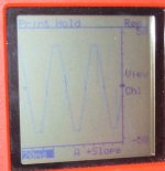
Some scope pics of a 9c motor with a 9 fet controller on 36 volts leads connected to two of the phase wires.

fullthrottle.JPG

partthrottle.JPG


24V is probably an average voltage reading. The peak voltage is going to be battery voltage minus drops in wires and FETs and such, very close to battery voltage. But because it is across two phases at a time, then depending on how you hook up the meter you may never see that. Plus, it is being PWMd to commutate sequentially thru the three phases, so even at full throttle you won't seen an average voltage of battery voltage levels on any one phase or even phase pair.

If all the phases are not working, the motor won't turn at all.

If you can, measure the no-load (wheel off ground) current from the battery to controller, while turning the throttle slowly up from zero to max. It should stay pretty low. If it is very high, the phase/hall connection order is probably wrong.

If it is too low a torque vs what it used to be, but it still reaches the same end speed eventually, then it is likely the controller you have now is a lower current-limit type than the original (18A +/-1A from it's label). Should be the same, or better, since it is 1000W which works out to 21A or so, but perhaps for some reason it is not doing that.


It is very strange that the original controller was a brushed controller (is labelled "brush") for a brushless motor. I expect it is a language problem.

It is normal for some connectors and wires on a controller to not be used.
 
Ya, its a lost cause. It seems you were lied to by the ebay seller. Anything out of china you should be cautious of.

Put a hold on the payment. See if you can get your money back.
 
Thanks all for the responses. Yep I've been testing it under no-load on a rack although when I first found a combination of hall/phase what worked I took it down the street and it's fine on level ground - but cannot do any incline - there's no torque.

My friend is an old Korean war vet and does not have a lot of money but we talked today and between new batteries, three controllers and a full set of new connectors I made - it's time for one of the better USA controllers - at least I think so. I'll be checking around tomorrow but if anyone has any recommended unit/sellers for a 48v/1000w please let me know.

bb
 
Remember that it is easily possible to find a "working" combination of phase/halls that doesn't actually work *correctly*, as it may have little pulling power but consume a LOT of current. There's 36 possible combinations, and typically only one forward and one reverse that actually work right.

Using a meter (DMM or wattmeter) between battery and controller is the easy way to tell if it's a false positive.

As for a "better" controller, the one you ahve now may work just fine. It might just have some connection, like a power limiter (often found on EU-limiting-capable controllers) and/or speed limiter (same) that is hooked up or not hooked up, that is causing the problem. OFten these limiters are loops of wire with just one wire into a two-pin connector, sometimes a single connector.

If you find you do still need another controller, I'd check out http://ebikes.ca and Lyen here on ES (he has several for-sale threads in the New section fo the marketplace).


EDIT (added): Also, make sure that under load you are actually getting 48V+ to the controller input. If you haven't checked that, it could be that the battery is actually not really outputting what it should. Not likely, but a possibility.

One more possiblity: if you can't even get the speed you used to out of it, you might also verify the throttle is working as expected. If it's a potentiometer type, it'll probably go from 0V to 5V. If a hall, from 0.5/0.8V up to 4/4.5V, somewhere in there.
 
Works smooth but no power is a false correct combo. Keep trying.
 
Each combination of phase wires will have 1 good combo of halls (the small wires) out of 6 possible. That good combo could be forward or reverse. You have what I call a false positive result, and on every motor I've had a false positive results in a good one in the opposite direction. Swapping 2 any 2 and only 2 phases changes direction, so my suggestion is swap 2 phase wires, and then find the good forward rotation of the other 5 combos of hall wires by swapping 2 at a time. Most run into problems by swapping too many wires at a time, which quickly gets frustrating. There are 6 good wiring combos out of 36 possible, one for each combination of phase wires, with 3 good forwards and 3 good reverses.

You can verify a good combo by checking the battery current going to the controller at no load. A good combo is reflected by low no load current, something less than 3amps typically. I say this because it's possible that the lack of torque could be coming from very low current limits of that cheapie controller, so check you no load current with the wheel off the ground first. False positives come with pretty high current. Measure battery side.
 
Great reply. Yes frustrating trying haphazard combinations. I have kept a log of the various combos I've found here and some other combs too. Definately what I would also call a false positive where on my lift where the motor seems to spin smoothly but almost no torque.

I have fouund a couple of combinations where it turns but chatters or almost grinds or sounds scratchhy. Other combos that just lock the hub.

But I have some combinations where there IS more torque but I can still hold the hub with some effort, reverse too.

I will go forward with two and only two as you suggested. Rest assured i'll contribe to this forum when its all resolved.
 
If you try all 6 hall combos without changing the phases and nothing with torque, then you probably have a bad hall connection, bad hall wire or bad hall sensor. Applying 5V to the red and black hall wires should give an alternating pulse up the other 3 as you turn the wheel and the magnets pass the 3 hall sensors.

Another possibility is a phase angle incompatibility. If the controller is set for 60° halls, but they are 120°, your result might be possible, but I've never had an incompatibility issue like that before to know for sure.
 
Just before I started this thread I checked continuity through all wires and connections all the way into the motor. On the Hall side up to the little circuit board transition into the windings. The Phase wired are in the back of the hub and I could not get that side off but I did check into continuity with a needle through the last point by piercing the sheath with a needle (and then resealing it too). The pictures in the beginning of this thread show where I was at. I continue to check continuity through the connections just to make sure something does not go bad or open.

60 or 120 degree was something I had not changed but the controller has two wires, open is 60, connected is 120. 120 is definitely badness.

I'm getting 5v on each of the Hall leads as the video below shows, a small drop as I increase the throttle and when I let off you can see the needle deflection.
HALL Video:
http://www.youtube.com/watch?v=AyrWBXqZgm4

PHASE VIDEO:
The Phase wires show an increase in voltage as I increase the throttle but max at 24v.
http://www.youtube.com/watch?v=fDZKEh5greY

I'm working up a matrix of possible connections and starting over.
 
In the phase video, I cna't tell where the other meter lead is going to. To read the full voltage, you must measure across any TWO phases, because that is how the voltage is being sent to the motor.

If you're measuring only one phase, to some other reference point, it probably won't show the full voltage.
 
bboulier said:
60 or 120 degree was something I had not changed but the controller has two wires, open is 60, connected is 120. 120 is definitely badness.

How do you know there's "badness" at the 120° angle? It will only have "goodness" on one combination of hall wires for each combo of phase wires.

bboulier said:
I'm working up a matrix of possible connections and starting over.

If you need a matrix, then you're definitely doing it the hard way. Slide the hall spades out of the motor side of that connector. Try the 6 combos of Y-G-B wires without changing any phase wires, only swapping 2 at a time. If you don't get a good forward or a good reverse, then change that phase angle plug to the other setting and try again. If you still don't get a good forward or reverse, then something else is wrong. If you get a good reverse, just swap 2, only 2, any 2 phase wires and find the correct combination of the remaining 5 hall combos (current one won't be right).

Be sure to use only small short pulses of the throttle on each attempt. If it's a rear wheel, take the chain off or look out for the pedal in case you hit a valid reverse.
 
If it turns out that you already have the best wiring combo possible then maybe it`s time to open the controller and add some solder to the shunt.
 
I've not updated this thread in a bit - thought I would.

I tried a lot of hall combos and still cannot get any torque out of it, the video's don't show it but I can hold the motor (it's a little hard to do but I can) and give it some throttle and it still only puts out 24v.

The eBay manufacture in China has been corresponding with me via email but language barrier really hard. Bottom line they have no idea about 24v and said they would replace it but I've not heard anything back from them. It took three weeks to get the first one...

So my friend who owns the bike (I gave him a computer a while back) has been checking the internet for options and came across GoldenMotor http://goldenmotor.com/ - another company based in China but I'll admit their website, information, specifications and overall documentation is HEAD AND SHOULDERS above the rest. Says they have a local distributor in NM I might give a call to.
 
the hall sensor leads should toggle on and off when you rotate the wheel. this is while the controller is connected, powered on, and the voltage on the hall sensor leads from the controller should toggle between around 5V and 0V.
 
Back
Top