Phase Amps to Motor Math

tedo

10 W
Joined
Dec 24, 2024
Messages
77
Location
florida
You guys were awesome at getting me to understand line amps vs phase amps in relation the battery and controller. But my math is not making sense on the motor side.

(What I got)
Fardriver 961800
QS268 Hub 20kw peak 40kw
Amorge 96v 64AH Lithium 400A Peak 640A

(My Math)
20kw/96v = 208 amps
40kw/96 = 416 peak amps

I was planning on using much more phase amps than that going to the motor obviously. Do I multiply those amps by 3 for a 3 phase motor to get the "Do not exceed" continuous phase amps and peak phase amps the motor can handle? I am not considering BMS limitations on this. Just wanting to know the maximum the motor can handle. I was planning on using 470 max line current and 1500 max phase current, but then my crayons gave me this:

(More of my math)
Continuous = 624 Phase Amps
Peak = 1248 Phase Amps
 
As mentioned in the previous thread, the simple equation of P = U * I doesn't hold for three-phase induction motors. You don't "multiply by three", as the currents across the phases sum up to 0.

There's no really no "peak phase current" limit on the wiring in a moment of time. Technically speaking, you could perhaps physically break the motor enclosure or bearings from the torque produced, but realistically such an impulse would still cook the wiring before it happened. As such, thermal buildup from heat losses remains the limiting factor for the engine power. It doesn't make sense to talk about "peak" because every peak can be different, and the highest value at any point of time doesn't really matter.

And to be frank, for the motor, neither does the continuous value. What if it's hot outside? What if you're moving uphill, slower, with less airflow? Those things could cook a motor at half the normally rated amps for continuous highway riding. So I'll repeat my earlier statements - don't rely on the math, make sure you have adequate thermal monitoring and cutoff and experimentally set the controller limits basing on those parameters and your power requirements.

It's no accident that KTM and Stark put water cooling on their motors. When selling to mass consumers, reliability is a major issue. They need a margin of safety, and without water, the motor would need to be prohibitively large to absorb the load during heavy use. But if you forego cooling capacity, it doesn't instantly mean that your motor can produce less power than their designs; it just means you have to pay more attention to how how it gets during operation.
 
On a dyno you would be able to tell when the motor starts to saturate and not produce the same torque per amp any longer, but it will be difficult on the street. Does it really matter?
When you start tuning you start low, maybe 100bA and 200pA. Then you gradually raise the amps. If the motor gets hot quick you can lower the pA and see if it helps, but you seem to have a big motor that can probably handle what you can throw at it.
I think you should focus on the bike, and a good clamp system to hold the motors axle secure in place.
 
So the reason Phase Amps are higher than Line Amps is NOT because there are 3 phase wires. It is because the motor is not taking 96v at low RPM and the math of W/V yields much more amps? Trying to understand this.

The hard parts I got down. Things like mounting the motor and swingarm etc. That is the only stuff I have figured out. LOL.
 
As mentioned in the previous thread, the simple equation of P = U * I doesn't hold for three-phase induction motors. You don't "multiply by three", as the currents across the phases sum up to 0.

There's no really no "peak phase current" limit on the wiring in a moment of time. Technically speaking, you could perhaps physically break the motor enclosure or bearings from the torque produced, but realistically such an impulse would still cook the wiring before it happened. As such, thermal buildup from heat losses remains the limiting factor for the engine power. It doesn't make sense to talk about "peak" because every peak can be different, and the highest value at any point of time doesn't really matter.

And to be frank, for the motor, neither does the continuous value. What if it's hot outside? What if you're moving uphill, slower, with less airflow? Those things could cook a motor at half the normally rated amps for continuous highway riding. So I'll repeat my earlier statements - don't rely on the math, make sure you have adequate thermal monitoring and cutoff and experimentally set the controller limits basing on those parameters and your power requirements.

It's no accident that KTM and Stark put water cooling on their motors. When selling to mass consumers, reliability is a major issue. They need a margin of safety, and without water, the motor would need to be prohibitively large to absorb the load during heavy use. But if you forego cooling capacity, it doesn't instantly mean that your motor can produce less power than their designs; it just means you have to pay more attention to how how it gets during operation.
None of this adds up. Not sure how the sum of anything except 0 can be 0. I'm living off Google AI here for answers. It tells me that phase "current" does not exceed line "Current", yet it appears to do just that with my 400amp of battery line current and 1500amps of phase current. All I keep seeing is; Phase current is line current multiplied by the square root of 3. That puts me at 692 Amps phase amps. A whole new number. Great. Still no idea how I am making 1500 phase amps out of thin air when I only start with 400 amps. The only way I can make the math work is if my 96v motor only gets 13v. While I get there are 3 phases, only one of those wires will have current for a given moment in time.

I still see absolutely zero rules for doing this. It just seems like a big guessing game. Toss some numbers in the Fardriver App and watch the heat as to not melt your motor. I like rules. This stuff cost too much money and seems too dangerous to just willy nilly guess at some numbers. The only thing I think I know for sure at this point is my battery will give a max continuous line amps of 400. So far I am just guessing at every other number entered. I am afraid to turn this thing on. LOL

Sorry that I keep on with this, but I spend hours reading threads on here and just do not find any consistency on rules for what to use for phase amps to the motor and why that number should be used. You said don't rely on the math, which I guess I can't. And to have thermal protection, which I do. So maybe I should just go for it blindly and see what happens.
 
It just seems like a big guessing game.
It kinda is. Engineering is about making educated guesses, after all. The more factors you include, the higher the likelihood of the correct answer, but reality is the ultimate verification.

Not sure how the sum of anything except 0 can be 0.
Heard of negative numbers? :) You're missing fundamentals for three-phase motor operation, that's why you find it so confusing. Take a look at the voltage graph:

1738967415644.png

Now look at any given point in time. You'll notice that two of the three phases are on one side of the ground, and the other is on the other. Two are pulling in one direction, the one in the other, and it sums to 0. E.g. take a look at the red top peak - at this point, the sum of green and blue is exactly equal, but opposite sign.

All I keep seeing is; Phase current is line current multiplied by the square root of 3
That's just wrong, if by "line current" you mean battery current. Again, as I've told you before, battery current is the current forced by the battery voltage over the resistance of the controller. Phase current is forced by the PWM-lowered battery voltage over the resistance of the motor windings, which is much smaller. Make the motor resistance arbitrarily small, and you can make the phase current be 10, 50, or a 100 times that of the battery current. Current, in amperes, just doesn't paint the whole picture. Since that current might be flowing at minuscule resistance, the power transferred to the motor will always be strictly smaller than the power pulled from the battery (with the small caveat of the controller filtering - otherwise, no controller is 100% efficient).

Read this again. Just because there's a lot of current, doesn't mean there's a lot of power being put into the engine - it's just a consequence of the motor characteristics and the controller adapting to them. Ultimately, what heats the engine up are the losses induced by the power being sent through the motor.

Now, does that say that you can safely ignore phase amps altogether? I would again say that realistically, pretty much, yes. J Bjork's suggestion to take it easy is a wise one - you can always increase the value once you test a lower one, that's always okay. There are things that might cause problems with the phase amps being too high - too thin motor cables come to mind. Limiting phase amps can also act as an effective low-speed power limiter, where the engine has the highest risk of overheating.
 
Google Ai is pretty poor when it comes to ebike info. The people programming it are stupid when it comes to them. Phase amps will always be higher than line amps if you are accelerating or under load, where the motor hasn’t achieved the speed the motor kv wants it to spin at. You could use formulas to explain it to yourself, but that doesn’t take into account that all controllers are not alike when it comes to their ability to deliver those higher phase amps. Even if two controllers have the same current specs, they don’t necessarily have the same phase amp capability. You’ll be able to tell that be the seat of your pants during acceleration between a controller that can deliver 3x phase amps compared to one that can only muster 2x.
 
@bananu7 , Your explanation is far better than mine, I am going to include it here for variety:

TL/DR: Battery amps and motor amps can be different because the VOLTAGE is different, same exact power/wattage, minus losses.

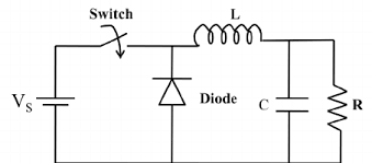
Think of your controller like a step down buck converter, it takes a higher battery voltage and a given amount of amperage i.e., a certain amount of wattage/power, and converts it to a lower voltage and higher circulating phase amps (same amount of wattage/power, as the battery side, minus losses) in the motor using a pwm duty cycle.
That is why motor amps can be as much as two to three times the amperage as on the battery side, but it's the same amount of power, just lower voltage and higher amps.

It works inversely during regen braking, controller acts as a step-up boost converter, pushing current into the battery.

The motor is the inductor/transformer in both cases, just like you see on any common dc-dc buck or boost converter.
 
You're missing fundamentals for three-phase motor operation, that's why you find it so confusing.
That is a fact I can understand. LOL. I have been watching tons videos on YouTube university, but to no real avail. I just need to go for it. Like you said, start small and I can always add amps later.
 
That is why motor amps can be as much as two to three times the amperage as on the battery side, but it's the same amount of power, just lower voltage and higher amps.
This actually makes me understand it. I was under the assumption that 96v motor always took 96v, but am realizing that is not the case even though 96v is going to the motor, it does not use all those volts. That mathematically allows the amps to be higher since the volts are lower. I can guess the voltage the motor uses is zero when stopped and 96v or whatever is available from the battery at full speed. Does the voltage run on a curve where it would be say 50 volts at 400 rpm for example?
 
The actual motor voltage (the voltage the controller presents the motor through PWM) doesn't just depend on RPM - it depends on the throttle, position, but also motor load.

The reason why you can only use lower voltage at 0rpm is exactly because of phase current limits. When the engine spins up, its back-emf adds up to the winding resistance, meaning that for the same power, the controller will need to use more voltage and achieve less current, meaning that it will stay under the phase limits, and will be only limited by the battery current limit.

If that wasn't clear before, phase current limit actually lowers the motor power at low rpm to that below the maximum power it can achieve at some higher rpm. Assuming no phase current limit set neither in the controller programming nor its hardware, the engine could theoretically produce all of its power (and massive torque) at standstill.

Just looking at the rpm will only give you the maximum utilizable, limited by phase current and power, voltage the engine can take. In practice, the controller will use its PWM capabilities to also include things like throttle signal and ramp-up time.

Another perhaps interesting tidbit is how it then affects the phases in sine vs FOC controllers, but up to the "PWM" stage it can be talked about as mostly similar.

@A-DamW the more the merrier; different explanations of the same thing can be very helpful because readers need different cues. I've also used the voltage converter analogy in my previous answer, so that part was spot on, especially how we end up getting high current at low voltage.

Some more explaining and I might start to understand it all myself.
 
@bananu7 ,
That is why motor amps can be as much as two to three times the amperage as on the battery side, but it's the same amount of power, just lower voltage and higher amps.
It can be even more like up to 20 times, it depends on how much phase current the motor and the controller can handle. The higher the phase current at low revs the more tourque you will have and the faster the scooter will accelerate.
From the graph from my fardriver the battery current is around 100A from zero rpm, while phase current starts with around 1200A. A little above zero rpm the controller regulates the phase current to my set 1400A and at 30kph the battery current reaches the set limit of 400A (32kw) , from there on the phase current has to be reduced to not stress the BMS and the battery to much and to not produce more power and heat in the motor to not burn the windings. My 10kw Motor would easily withstand short 40kw bursts, but my BMS only when they are shorter than 13seconds. I killed one during a stationary test with an electronic load while I was trying to find the limits. I suceeded 😉.
Screenshot_20240216_102245.jpg
Test was done with a A123 Lifepo pouch pack from my Kids kettcar, which was converted to electric.
BMS test to deathLink to the test (in german)


If I would reduce phase current to 700A the battery current limit would first be reached at 60kph and acceleration would be much slower.
 
Last edited:
This thread began with the idea that math about amperage/motor response might save a motor from overheating. Real world motor overheating is monitored by adding a thermocouple/thermistor to the place in the motor most likely to get the hottest/the quickest. From the thermistor signal one can read a temp gauge or with a SSR (solid state relay) (low voltage actuation) have high temps shut the motor off— not much power engineering needed.
 
Last edited:
Awesome stuff guys. Thanks so much. I just figured out my DKD display does not even show motor temperature. Didn't realize that when I bought it. I will have to view the app also so I can monitor that. That seems like the most crucial thing.
 
Google Ai is pretty poor when it comes to ebike info.
I found this explanation very helpful during the development of the EBiCS firmware. It shows how the center aligned PWM works in a FOC controller quite good.
https://www.switchcraft.org/learning/2016/12/16/vector-control-for-dummies

All the witchcraft is to set the right duty cycle at the right time ;)

regards
stancecoke

image-asset.gif
 
I found this explanation very helpful during the development of the EBiCS firmware. It shows how the center aligned PWM works in a FOC controller quite good.
https://www.switchcraft.org/learning/2016/12/16/vector-control-for-dummies
Good article. There are quite a few articles out there that attempt to explain the concept, but it really takes reading a lot of them before something triggers the right logic in the reader to have it makes sense. Could be different for different people. For me, the concept of the stator windings being inductors, and how switching the current on and off results in reactive current helped me think about the “why”, more than explaining it by formulas.
I’d love to see this thread result in a description that is easily digestible for the moderately experienced DIYer (to add to my FAQ lol).
 
You can not make an omelette without cracking a few eggs, same for motors there will be mistakes.

Lessons learned is the aim and always listen for a clean stable sound no unwanted vibrations thats the biggest give away.

The motors I've murdered have failed by to many initial amps learnt that one quick, then revving a motor out past its rpm point and fracturing a magnet then same again at close to saturation point for extended periods of times allowing me to cook the omelette i mentioned in the first place.

Main point i want to add is keep close to specs of a motor and use gearing to get the best out of a ride but remember that messing with flux weakning after setting gear ratios can be a combo to death as torque is reduced at higher rpm and a fearce gear ratio will also add heavy loading and rapid heating.
 
Good article. There are quite a few articles out there that attempt to explain the concept, but it really takes reading a lot of them before something triggers the right logic in the reader to have it makes sense. Could be different for different people. For me, the concept of the stator windings being inductors, and how switching the current on and off results in reactive current helped me think about the “why”, more than explaining it by formulas.
I’d love to see this thread result in a description that is easily digestible for the moderately experienced DIYer (to add to my FAQ lol).
I have found this diagram below explains how the controller and motor inductance combined can be compared to a buck converter to increase the motor current above the battery current. Its worth noting that the top three mosfets are subject to different stresses than the bottom three and that pulse width modulation (pwm) mainly takes place on the left side (lower rpm) side of the peak of the power curve.
pwm.jpg
Basic buck converter below.
buck converter.png

I found the notes below very helpful.
 
Last edited:
Back
Top