Phase Amps VS battery Amps, mosfet controller

yabert

100 W
Joined
Apr 23, 2016
Messages
102
Hi

Looking for explanation here.
I'm trying to understand why some controller manufacturer rated their product with higher phase amps than battery amps.
And some other manufacturer only rated amps (no battery or phase specified).
Some example:
Nucular24: max phase current 500A, max battery current 350A
3Shul700: 700A phase, 350A battery
Go-FOC G300: 500A phase, 250A battery

What happen to mosfet at 100% pwm? I mean, 300A battery or phase will heat the mosfet anyhow. So how most controller are rated for 2X more phase amps than battery amps?
I can understand that higher phase amps are useful for acceleration of motorcycle, car and other stuff. But at full speed?
Sure it's power in/power out (minus controller lost), but why it not like: 300A 72V battery (21.6kW) = 21.6 kW / 300A share between 3 phases.
Please let me know.
 
At 100% PWM, the phase amps will be about equal to the battery amps. At less than 100%, the phase amps will be higher than the battery amps as it's working like a buck converter. Phase amps can be 3x the battery amps or more at low PWM. The controller software typically limits both to keep the FETs from blowing up.
 
At 100% PWM, the phase amps will be about equal to the battery amps.
Thanks, it's also what I understand.
But I would like to learn/understand why many controller are rated for around 2X more phases amps continuous than battery amps continuous.
 
why many controller are rated for around 2X more phases amps continuous than battery amps continuous
Because you will not have 100% duty cycle in most cases. Only near top speed this will happen, where all voltage from the battery is needed to overcome the BEMF.
The grin motor simulator is a nice tool to understand the dependencies of speed, load, torque....

regards
stancecoke
 
Because you will not have 100% duty cycle in most cases.
Yeah, this is true for most EV. But it's not the case for a properly designed boat when you can be 100% duty cycle for hours.
So, I tried to wrap my head about how mosfet will heat less at, let say, 300A phase than 300A battery.
 
So, I tried to wrap my head about how mosfet will heat less at, let say, 300A phase than 300A battery.
If this is at 100% duty cycle, there should be no difference. But this would be only at one single working point it would be an absolute coincidence to hit that point. I set max battery and max phase amps to the same value in this example.
 
Last edited:
If this is at 100% duty cycle, there should be no difference.
This is the part I'm not sure to understand.
So, that way it's like saying that most controller manufacturer rated they product at 2X more phase amps than battery amps, but in fact all controller only can output 1/2 rated phase amps continuously.
 
Except if I design cruising speed of a boat to reach 100% duty cycle by selecting proper propeller, motor/voltage/controller.
Even on a boat this is a very theoretical case, where the motor speed is exactly that high, that the motor- and phase current are the same and at maximum. With a little tailwind, the rpm will increase and the motor will draw less current. With a little headwind the rpm will decrease, and the battery current will get lower than the phase current....

There was a similar discussion a few years ago...
 
Last edited:
Thanks for the link.
If I understand correctly, controller manufacturer can rated continuous phase amps at around 2X more than battery amps because anyway the motor can't take more amps without more volts.
So, by example, the 3shul 84V 700A controller can not be a 58.8kW controller because anyhow the 700 phase amps will start to decrease at around 1/2 battery voltage, so it's a 29.4kW (350A x 84V) controller or a 29.4kW (700A x 42V) controller.
Right?
Trying to put this simply...
Battery amps ≈ phase amps x duty cycle

Therefore, give duty cycle is 0 to 1... Battery amps cannot be higher than phase amps.

Phase amps are what causes mosfet heating. The entire phase current flows through the mos, regardless of the duty cycle.


Controller manufacturers usually rate the battery amps lower than the phase amps for no sensible reason. The number of battery amps is simply a mathematical abstraction of the phase amps and duty. Some controllers struggle at high battery amps because the electrical noise gets higher at higher current and also at higher duty... Hence they fail at high battery amps.

Because of this, and the difficulty of testing at extreme power levels because of power supplies and motor availability, there's become a trend of suppliers guesstimating the battery amps based on the low duty phase they achieved on the bench and the typical "about half" everyone else seems to cite.
I'll note that it's not as simple as above strictly, as well as the phase amps and duty cycle you need to consider the power factor or phase angle between the voltage and current.

In FOC math terms we write
P = Vbat x Ibat = 3/2(Vd x id +Vq x iq) where the phase angle is the angle between (Vd+jVq) and (id + jiq)

Duty cycle is 1 when mod(Vd + jVq) = Vbat/sqrt3

Phase current is iq normally (id =0) but in MTPA or field weakening becomes mod(id+jiq)

Hope this clears things up for you...
 
Hope this clears things up for you...
No :ROFLMAO:
I prefer your simpler explanation above 😄

I tried to understand all this because I plan to choose a simple ''motorcycle'' controller for a boat project.
Controller like: ASI BAC, VESC, 3Shul, EZcontrol or Nucular.
But, other parts are: 160 kWh NMC battery (58V) and Nissan Leaf motor... so both have WAY more potential power than small controller.
Power requirement is small (10-15 kW max), but for 10-15 hours 🫤
I mean that motor is way way overkill but I guess there isn't anything wrong with that, most of these large controllers are designed to be plate cooled so a water cooling plate would keep them nice and cool. I'm not sure of the efficiency of running a large motor so far below it's intended RPM and load though. At a voltage so far below it's intended operation range (360v) it's going to spin much slower than it was designed and pushing lot of current into it will be hard due to the high resistance and inductance.
 
it's going to spin much slower than it was designed
That the main goal for a direct drive application (around 1000 rpm propeller).
I started designing around Motenergy ME1905 + a planetary gearbox when I realize that Leaf or Kona EV motor are more rugged and cheaper while allowing to skip the gearbox (y)

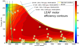
Here (green line) a rough power curve I've estimated from the Leaf motor at 58V.
I start to think that I will be limited to a lower 12-15 kW.
1746228226604.png
 
I don't think the 3Shull 700 will be able to run at 20kW for hours.
I have a fardriver ND721800 in my scooter, this Controller can do 60kW peak and is advertised for motors with 10-15kw continious power.
 
Last edited:
I don't think the 3Shull 700 will be able to run at 20kW for hours.
I'm a bit surprised and sad when I read this.
I slowly start to understand the problem is not my low comprehension of the mosfet in a BLDC controller, but it's more related to the rating give by manufacturers 😑

Last years, a good choice I've found was a 800A EZkontrol.
800A!!! That is serious current so, at 60V, it will be able to drive my motor at 15 kW without problem... Well, no it rated for 5-8 kW motor 😳
Now, same thing here with Fardriver: 1200A!!! It's awesome, no? Well, no because it rated for 8-12kW motor 🤯

And a VESC 75/300A? It's 300A or it for child toys motor only?
1746379441413.png
 
I'm a bit surprised and sad when I read this.
I slowly start to understand the problem is not my low comprehension of the mosfet in a BLDC controller, but it's more related to the rating give by manufacturers 😑

Last years, a good choice I've found was a 800A EZkontrol.
800A!!! That is serious current so, at 60V, it will be able to drive my motor at 15 kW without problem... Well, no it rated for 5-8 kW motor 😳
Now, same thing here with Fardriver: 1200A!!! It's awesome, no? Well, no because it rated for 8-12kW motor 🤯

And a VESC 75/300A? It's 300A or it for child toys motor only?
View attachment 369717
VESC 75300 is not for 300A continuous. Maybe 175A with a water block continuous.

Normally controllers are used for electric vehicles so the peak power needs to be high but the continuous cruise power is 5x lower typically.

Your boat is an unusual application. You need a big controller and a water cooling loop.
 
Normally controllers are used for electric vehicles so the peak power needs to be high but the continuous cruise power is 5x lower typically.
Fully make sense... sadly.

Your boat is an unusual application. You need a big controller and a water cooling loop.
I'm open to suggestions.
So, 500$ Leaf motor with 2k$ controller 🤔
 
Last edited:
This is sadly the problem, controllers normally cost much more than motors and when you are talking about a used leaf motor which is already probably way way cheaper than it would have been new. This is also why high power motors are often designed around higher voltages so you can use a lot less current, now it's not quite that simple but there is some level of balance, very high current and low voltage in inefficient, so is high voltage but very low current. It just so happens there is kind of a real lack of mid voltage controllers in the 100-200v range maybe due to the market and weird voltage things with mosfets and IGBTs not currently being optimized for this voltage range.
 
there is kind of a real lack of mid voltage controllers in the 100-200v range
I understand, but at the same time I absolutely not looking for this kind of inverter as I want to stay compatible with all 48V solar stuff.
To me, 10-15kW (167-250A) was compatible with low voltage controllers as they are rated for 450-1200A. But it's seem this ''fake'' rating is exclusive to lightweight vehicles.
Honestly I think most of these controllers that are rated for 500+ amps continuous would be fine if they were water cooled, of the controllers you listed I think only the 75300 would maybe struggle at 250A continuous. Yes in many vehicle applications some of these controllers are unable to output their ratings for long periods of time but those are with air cooling, water cooling can remove a hell of a lot more heat. I mean a lot of efoils use these large VESCs at those power levels all day long. I don't have any experience with this application as do many of us here so you may want to find some examples of actual water cooled continuous boat/efoil applications.
 
Controller manufacturers usually rate the battery amps lower than the phase amps for no sensible reason. The number of battery amps is simply a mathematical abstraction of the phase amps and duty. Some controllers struggle at high battery amps because the electrical noise gets higher at higher current and also at higher duty... Hence they fail at high battery amps.

Because of this, and the difficulty of testing at extreme power levels because of power supplies and motor availability, there's become a trend of suppliers guesstimating the battery amps based on the low duty phase they achieved on the bench and the typical "about half" everyone else seems to cite.
Thanks for that explanation, I have never really understood why there should be a limit for battery amps in the controller.
Sure, for the batteries sake etc. but not why it would be a problem for the controller except for heat, as it could mean high pA for longer time.
 
Back
Top