Poor man's 15 Amp battery charger?

I love this idea its so simple! I think with some redundant safe guards and H V C , it could work. I have to try it on my headway pack, not sure how this dirty power will effect, the cell logs I use.

The parts list is growing. Fuses for A C and D C , D P D T relay and switch, and more caps from motors and H D lighting. Easy junk finds.

Hope this thread dose not die!
 
Heres a few pictures of my setup, its a mars brand 72-88uf ac capacitor, an 8a 400v bridge rectifier, and two 330uf 250v caps on the output.

2012-02-13130710.jpg


2012-02-13130646.jpg
 
V2 of this guy has been built. Goes in a a 240v outlet, outputs 55a @ 100v and weighs 4 pounds :twisted: :twisted: . 16 min charge on a 1330 wh/hr pack :D .
 
wow. This is very cool. I want to sub it so I keep updated. But, I think I'll wait the month or so of coursework until I better understand it.
 
Farfle said:
V2 of this guy has been built. Goes in a a 240v outlet, outputs 55a @ 100v and weighs 4 pounds :twisted: :twisted: . 16 min charge on a 1330 wh/hr pack :D .

Very nice. I want a 240V outlet, 28-30Adc version; what parts did you use?

Goal is a quick opportunity pack charge to 85V. For awhile I was pondering getting a 4:1 step down transformer to convert the 240Vac to 60Vac; then rectify it to 84.8Vdc; bingo - perfect bulk charger. But they want two arms and a leg for these transformers and too heavy.

Still would like to find a away to clamp the output voltage to 85V. Do they make 50A, 85V Zeners? The BMS cycles during the charge and not sure it will be happy seeing 340V when no current is flowing. I guess I could bypass the MC & BMS; use Cellog for HVC instead.
 
Regulating the output could be difficult. For a zener clamp to work, it would need to handle the full power. Anybody seen a 5kW zener diode?

I don't think you could use a SCR/Triac type light dimmer with the series capacitor setup either since the SCR turns on suddenly and will have a very fast rise time, which will cause a huge current spike through the capacitor. Maybe with an inductor in series it might work.

I think a more practical approach would be to place a large solid state relay in series with the AC line and use a small control circuit to turn the relay off when the output voltage exceeds a preset value. A circuit to do this is fairly simple. It could simply latch off when the limit is reached and start with a manual push button.
 
fechter said:
Anybody seen a 5kW zener diode?
I found a 5KW TVS...does that count?
http://parts.digikey.com/1/parts/1764696-tvs-5kw-unidir-160v-5-p600-5kp160a-e3-54.html

However, that's *peak* power, not continuous.
"5000 W peak pulse power capability with a 10/1000 µs waveform, repetitive rate (duty cycle): 0.01 %"

Some more for different voltages:
http://parts.digikey.com/1/parts/1764693-tvs-5kw-unidir-15v-5-p600-5kp15a-e3-54.html
 
fechter said:
I think a more practical approach would be to place a large solid state relay in series with the AC line and use a small control circuit to turn the relay off when the output voltage exceeds a preset value. A circuit to do this is fairly simple. It could simply latch off when the limit is reached and start with a manual push button.

Hy Fechter, could you help me with that circuit? I have no idea how to build one. A scheme and wiring plan would be nice.
 
IBScootn said:
Very nice. I want a 240V outlet, 28-30Adc version; what parts did you use?
Goal is a quick opportunity pack charge to 85V. For awhile I was pondering getting a 4:1 step down transformer to convert the 240Vac to 60Vac; then rectify it to 84.8Vdc; bingo - perfect bulk charger. But they want two arms and a leg for these transformers and too heavy.
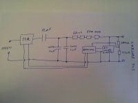
The voltage will adjust. For reaching the 30Amps, you might need a 500 µF AC capacitor or different lower capacity pieces put in parallel. To rectify that current you can use the bridge rectifier mentioned in my first message.
 
fivari said:
Hy Fechter, could you help me with that circuit? I have no idea how to build one. A scheme and wiring plan would be nice.

This is about as simple as it gets without going cave-man mechanical relay approach.
Calculate R1 for your maximum desired voltage using the formula. VR1 gives a 10% downward adjustment range. Maybe add 5% to your max voltage to make VR1 centered.

The start button activates the solid state relay and powers the charger. When the voltage reaches the cutoff point, the LM431 pulls down the input to the TPS2812 and turns off the relay. R4 makes it latch off. The LED and HVC input are optional. Grounding the HVC input will also turn the charger off, if you have cell level monitoring.

Other than the 12V power supply and relay, the rest of the parts would fit on a very small perf board.

The 12V power supply can be almost anything and only needs to supply about 25mA.

This circuit will work with ANY battery charger as long as the SS relay is sized properly.

ALWAYS USE A FUSE! A GFCI breaker is highly recommended for non-isolated chargers.
Bad Boy Charge Controller.jpg

Some of the fancier SS relays have built-in zero crossing detectors that force it to turn on only during the zero crossing. It may actually be possible to crudely regulate the output voltage using one of these by omitting R4 in the schematic. As long as there is a load, the relay will turn on/off to keep the output voltage at the set point.
Personally, I would prefer the latching cutoff.
 
Very nice, thanks Fechter.
 
fivari said:
Thanks Fechter, I already bought the LM431 and TPS2812 components to build one.

Cool. I'll be interested to see how it looks.

About the only tricky part will be setting the cutoff voltage. I think to do it right, you'd want to apply the exact cutoff voltage to the input pins, then adjust the pot until it just turns off.
You could possibly do this by using the pack in series with a variable power supply to get the right voltage. It might take several tweaks to get it dialed in.

If the charging current is relatively high, then the cutoff voltage can be a little higher than you'd normally charge to because of the 'reverse sag' of the batteries. Once it cuts off, the voltage will immediately drop. This is how many small lithium chargers behave.

To be safe, you could always dial in a slightly low cutoff voltage. This will cutoff before you reach full charge, but hitting 90% should be good in most cases.

If there is no load, it should cut off almost immediately. You could still be left with a lethal charge on the output caps though. It would be good practice to place some kind of bleeder resistor (or light bulb) across the caps to drain the charge when turned off. I'd be curious to see how much over the normal cutoff it goes to with no load. In theory, it could go to nearly the rectified line voltage on just a few AC cycles.
 
Farfle said:
V2 of this guy has been built. Goes in a a 240v outlet, outputs 55a @ 100v and weighs 4 pounds :twisted: :twisted: . 16 min charge on a 1330 wh/hr pack :D .

I used two of these for output:
http://www.ebay.com/itm/140647124550

With a 12uF motor run cap they lasted about 30min @ 93V battery voltage before making my whole flat smell bad. Should I use higher voltage rating or a different type of caps?
 
I don't think an output cap will help. The ESR of the cap will most likely be higher than the internal resistance of the battery pack, making it pretty pointless to put it there.
 
I suppose you didn't put these two in series, but in parallel to the output. I guess the limit voltage (100V) is somewhat close to the battery voltage (93V). Add the reverse drop when charging and your reserve is gone.
I used 400V DC capacitors.
 
I think I found the problem. After the caps I put 24ohm resistor to make it even more stable. At 0.55A that was 13.2V on the resistor and 92.7V the battery. That's 105.9V in total, so no wonder they fried ;)
 
dnmun said:
oh details, details.


this got me thinking of my first science project when i was about 14, back in 1960. back then they wanted everybody to become a scientist so we could beat the russians to the moon. even before gingrich decided to go to the moon.

anyway, ramjets were big in all the popular science magazines so i decided i would build a ramjet for a science project, using the gas bunsen burner in the lab for the fuel source. i found a length of downspout to make the "cylinder" of my ramjet, and put the bunsen burner underneath with the tube pointing to the ceiling of the lab. no pretesting so the ignition source i rigged up from a 12V doorbell transformer with the 120V wall source applied to the 12V windings and the high side, the 120V but now really 1200V, was inside this cylinder with a big spark gap to achieve ignition so my ramjet would work.

so i went in early and was setting it up on the bench, turned on the gas and tried for along time to get the ramjet to ignite, but the igniter would never make a spark. so it never got lit.

i still remember how dejected i felt that i had failed to get my project to work, the ramjet cylinder never ever lit in spite of my pushing tons of natural gas from the bunsen burner through the cylinder into the room for about 15 minutes before i gave up.

this is back when we had floor to ceiling windows, overlooking the schoolyard where everybody was coming to school that day.

i coulda been famous. failure sometimes has been a blessing.

That is funny. I did something very similar when I was a kid. I did get ignition, but all I had was a heater. Mine was based on home heating fuel, a small pump, and a furnace igniter. I imagined powering my sled with it (would have to work out the problem of keeping the ignitor plugged in). Can you imagine a rocket powered sled? That would have been the envy of the neighborhood. Then I read that ramjets have to get shockwaves at the inlet so I would have to get my sled up near Mach 1 first. Then started looking at "buzz jets" with a reed valve at the inlet. Got too complicated for a 10 year old at that point.

PS: I later got a BS and MS in aerospace engineering so I was a rocket scientist (actually engineer) after all.
 
The output caps might still be useful as this should help prevent the batteries from heating due to the ripple current. I remember one report of the battery cells actually 'buzzing' due to the high ripple current. I don't think this is good for the cells.

The output caps should definitely be rated for the full rectified line voltage as this could happen if you disconnect the load.

The output caps will still see a high ripple current even with cells connected and might get pretty hot if they have a high ESR. Another motor run cap used as an output cap might work OK. I'm not sure what the specs on those look like though.
 
If we neglect ESR of the cap, we have the RC constant of the output cap and internal resistance of the battery pack to smoothen the current. The cap will only make a noticeable difference if the RC time is as long as the distance between the pulses from the rectifier, or longer. Pulses come at 100-120 Hz, or about 0.01seconds apart. If battery IR is 0.01 ohm, then the cap needs to be about 1F. If battery IR is 0.1 ohm, then cap needs to be about 0.1F. Thats pretty big caps, especially if they need to be rated 400V.

I think I'll make mine without output caps.
 
I've replaced them with 2 x 200V 1000uF. I'll test it and post the results.

bearing said:
If we neglect ESR of the cap, we have the RC constant of the output cap and internal resistance of the battery pack to smoothen the current. The cap will only make a noticeable difference if the RC time is as long as the distance between the pulses from the rectifier, or longer. Pulses come at 100-120 Hz, or about 0.01seconds apart. If battery IR is 0.01 ohm, then the cap needs to be about 1F. If battery IR is 0.1 ohm, then cap needs to be about 0.1F. Thats pretty big caps, especially if they need to be rated 400V.

I think I'll make mine without output caps.

You can try my way, just put a power resistor in series with the battery. 24ohms is 240x 0.1ohm. Then you need a 416uF cap.

My messy 2nd try:
file.php


As you can see I have an Arduino monitoring the state of charge and it should turn off when charged.
 

Attachments

  • 2012-03-07 10.12.09.jpg
    2012-03-07 10.12.09.jpg
    241.3 KB · Views: 902
I guess that works at lower charge currents. But if you charge with 10A, then a resistor of 24 ohm would dissipate 2,4kW. Even a resistor of only 1 ohm would dissipate 100W, which is a lot IMO. I generally don't like the idea of burning away energy through resistors. As long as the peak of the current pulses aren't far above the maximum charge rate of the battery, I don't think it's a problem to omit the output caps.

Good idea to put an MCU in it! But please put the MCU on a simple board, with some decoupling caps and a stable supply! =) your AD measurements will probably be all over the place with that design.
 
OK, that was no help :(

This might be a little clearer:

file.php


As long as the peak of the current pulses aren't far above the maximum charge rate of the battery, I don't think it's a problem to omit the output caps.

You might be right. I'm just not ready to sacrifice my new battery. My intention is to charge at 3A max.
 

Attachments

  • 2012-03-07 11.13.57b.jpg
    2012-03-07 11.13.57b.jpg
    38.8 KB · Views: 1,050
Back
Top