You are using an out of date browser. It may not display this or other websites correctly.
You should upgrade or use an alternative browser.
You should upgrade or use an alternative browser.
Powerchair Direct Drive Brushless Motor (High-Torque)
- Thread starter amberwolf
- Start date
[youtube]Vhnbw6nNpGc[/youtube]bigmoose said:Amber before you go too far, put 5V and Gnd on the pins and scope the Sin and Cos simultaneously while spinning the motor and make sure you get the functions out in analog. What is neat if this is true Sin and Cos is that one could build and advance function pretty easily... easily being a pejorative of course! If you get Sin and Cos the next question is to figure out how they are doing it so cheaply and reliably.
[youtube]G358NcDOO1s[/youtube]
liveforphysics
100 TW
You totally rock Amberwolf!
And this motor looks like a beast! That should be capable of a ton of power, and looks like a pretty quality design and build.
And this motor looks like a beast! That should be capable of a ton of power, and looks like a pretty quality design and build.
And these motors are all over the place on all those newer powerchairs--the ones with two large center wheels and four outer "caster" wheels. Not all of those have these motors, but the larger ones and higher end ones should.
As I understand it, the places that service these may not be able to get replacement parts for the brake assembly, so they may just toss out the WHOLE MOTOR ASSEMBLY when the brake wears enough to start slipping. After all, medical insurance / medicare pays for the repairs of the equipment, so the end-user doesn't have to foot the expensive bill for that....
So...go hunt down your local repair places and see what kind of deals you could make.
As I understand it, the places that service these may not be able to get replacement parts for the brake assembly, so they may just toss out the WHOLE MOTOR ASSEMBLY when the brake wears enough to start slipping.
So...go hunt down your local repair places and see what kind of deals you could make.
After I get the chance to open it up and find the screw that came out of the handle pivot, I'll use this latest donation from a local friend to try to capture both signals at the same time:
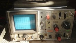
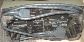
It's a Hitachi V209 portable oscilloscope, although I don't know if the battery still works or not (easily fixed if it doesn't ). Since it can be powered by external 11-14V, too, I could power it off my lighting pack on CrazyBike2, if I needed to take it somewhere for off-grid troubleshooting or repairs or something (like at a racetrack, though hopefully nothing would require a scope at a track!).
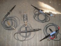
It came with two presumably Hitachi probes with 1x/10x switches, as well as a Tektronix standard probe and a Tek current probe (so now I have two Tek current probes...that could come in handy someday, like for comparing phase currents?).
There was also an ammo can and some other assorted electronics, including a bunch of TO-3 style 7812 voltage regulators (and a few TO220 7812s).
View attachment 3
Some TO-3 style 2N6285s, which are PNP Darlington comp-pair transistors, rated at 10A 60VDC. Some 2N6282 same family NPN style.
Some TO3 style 2N5875s, PNP 60V 10A power transistors.
Some triacs, TO202 style, L6004F51, 600V 5A.
Some triac drivers, 6-pin DIP, MOC30411 which are zero-crossing detecting and optoisolated.
Guessing these were all for PSU repair, or control system repair. I'm sure I'll figure out something to use them for.

It's a Hitachi V209 portable oscilloscope, although I don't know if the battery still works or not (easily fixed if it doesn't

It came with two presumably Hitachi probes with 1x/10x switches, as well as a Tektronix standard probe and a Tek current probe (so now I have two Tek current probes...that could come in handy someday, like for comparing phase currents?).

There was also an ammo can and some other assorted electronics, including a bunch of TO-3 style 7812 voltage regulators (and a few TO220 7812s).
View attachment 3
Some TO-3 style 2N6285s, which are PNP Darlington comp-pair transistors, rated at 10A 60VDC. Some 2N6282 same family NPN style.
Some TO3 style 2N5875s, PNP 60V 10A power transistors.
Some triacs, TO202 style, L6004F51, 600V 5A.
Some triac drivers, 6-pin DIP, MOC30411 which are zero-crossing detecting and optoisolated.
Guessing these were all for PSU repair, or control system repair. I'm sure I'll figure out something to use them for.
Easy enough to find the loose part; was just a brass disc for the handle screws to thread into. reinstalled n handle and fixed that.
Noted this scope has seen some action over the years, but it does still work at least on AC.
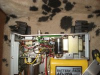
Internal NiCd (12V 1.8Ah) isn't charged up enough to run it, and I don't have a cord to hook up to the scope's 12V input. It's kind of like a laptop two-pin AC cord, but square on the sides instead of rounded, and is quite a bit deeper than any of the cords I have. So I'll have to make one up for it.
View attachment 1
According to the specs, it does only take about 800mA on DC to run the scope, so it's pretty low power, at only about 10W power usage typical. It only charges the NiCd with trickle charging, at 180mA, and says it takes 12-13 hours for a full charge. On discharge, it cuts off at 10.2V. At 800mA, with 1.8Ah, I guess it has something less than two hours of runtime on battery, depending also on self-discharge of cells, etc. and how long it has been since they were last charged.
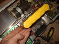
Anyway, it powers on and both traces respond to input, so once I have a bit more time I can see about using another motor to spin up that power chair motor (maybe friction drive against the front wheel of CrazyBike2 or DayGlo Avenger) while videoing the scope monitoring both sin and cos hall outputs.
Then I need to wire up the new 3 halls for power, ground, and signal, and mount them up at a physical 120 degree spacing (for simplicity). I'm not sure exactly where they need to go relative to the stator, so I will mount them on a ring that I can rotate and then glue into position once I figure out where they should be. (unless someone here has a good starting point idea, I'll start with them between stator teeth, as opposed to centered on them).
Then figure out the phase/hall combo on one of the controllers, and see if I can make it work on ebike controllers.
Noted this scope has seen some action over the years, but it does still work at least on AC.

Internal NiCd (12V 1.8Ah) isn't charged up enough to run it, and I don't have a cord to hook up to the scope's 12V input. It's kind of like a laptop two-pin AC cord, but square on the sides instead of rounded, and is quite a bit deeper than any of the cords I have. So I'll have to make one up for it.
View attachment 1
According to the specs, it does only take about 800mA on DC to run the scope, so it's pretty low power, at only about 10W power usage typical. It only charges the NiCd with trickle charging, at 180mA, and says it takes 12-13 hours for a full charge. On discharge, it cuts off at 10.2V. At 800mA, with 1.8Ah, I guess it has something less than two hours of runtime on battery, depending also on self-discharge of cells, etc. and how long it has been since they were last charged.

Anyway, it powers on and both traces respond to input, so once I have a bit more time I can see about using another motor to spin up that power chair motor (maybe friction drive against the front wheel of CrazyBike2 or DayGlo Avenger) while videoing the scope monitoring both sin and cos hall outputs.
Then I need to wire up the new 3 halls for power, ground, and signal, and mount them up at a physical 120 degree spacing (for simplicity). I'm not sure exactly where they need to go relative to the stator, so I will mount them on a ring that I can rotate and then glue into position once I figure out where they should be. (unless someone here has a good starting point idea, I'll start with them between stator teeth, as opposed to centered on them).
Then figure out the phase/hall combo on one of the controllers, and see if I can make it work on ebike controllers.
Got the video of the sin/cos sensors working with the motor spinning (powered by friction drive from CrazyBike2's front wheel), and also of the motor's phase wire waveform the same way.
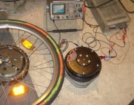
Test setup was very simple, just the lab supply for 5V on the halls, then Ch1 of the scope on one hall and Ch2 on the other. Signal ground provided by a lead from scope's Trigger input ground to the lab supply ground. Both channels are on 2V/cm. Ch1 zero is center of screen, Ch2 zero is bottom of screen.
[youtube]xlEFwQAygYM[/youtube]
Phase waveform test is just ground of Ch1 on one phase, signal of Ch1 on another, Ch1 on AC input setting and 5V/cm (max this scope goes to) and zero is center of screen.
[youtube]HaNUvz06zrc[/youtube]
Unfortunately until after I had already put everything away, I didn't think of measuring the actual voltage output from it vs a specific wheel speed, which I could have used to calculate what kind of (unloaded) voltages I could generate from the motor from BEMF at various speeds. Maybe I'll measure that later, when I have it set up to test the three-phase halls once they're installed.
Been doing some searching of ES regarding trapezoidal vs sine BEMF, and I am not quite sure I understand it all. But if I do understand it right, this motor would be much better driven by a sine controller since it has sine BEMF, rather than a trapezoidal controller like most ebike controllers (including all the ones I have here, AFAIK).
Also been trying to figure out an easy way to determine the winding resistance and inductance. Since I have that big Sorenson with adjustable voltage and current limit, I should be able to use that and a voltmeter across a pair of phases, plus Ohm's law, and calculate the resistance for a pair of windings and divide by two.
But I don't have anything that will measure inductance at all, so what I was pondering was using a signal generator (which I have around here somewhere, if it works) to pass a specific amplitude and frequency thru a pair of windings, and see if it is delayed by an amount I can measure on my scope, and maybe calculate it from there? I have to look up the procedure for doing this, because I am probably forgetting an important step or component, like having a known capacitance in there, too. I remember doing it in the lab at school, as one of the lessons, but that was 1988 and I don't think I have done it since then.
I took teh hour or so today to wire up and test the hall sensor idea, but there is no way to read the magnets from the place I wanted to put them (for ease of figuring out positioning without opening up the motor repeatedly). That would've been on the lip of the mounting box, where the red arrows point.
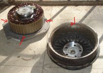
I should have tested for that before doing all the wiring for all three sensors and rigging up the scope and multimeter for monitoring, and digging out this 36V 12FET to run the motor with:
http://www.endless-sphere.com/forums/viewtopic.php?f=4&t=21830
but naturally I didn't think of that, and just started setting up and playing around, then finding there was no hall signal changes happening.
I can't get readings from outside the rotor (behind or either side of the flux ring), as there's not enough flux leakage to trigger the halls from any position I could find.
If I could get them up inside the rotor and still move them around from outside, I could get them up about 3-4mm from the ends of the magnets and it'd still work, but the gap is too narrow for the wire insulation; it'd rub thru it, especially since I wouldn't have it glued down during the experiments till I figured out positioning.
I could machine off enough of the inner lip of the rotor housing (see red marking on rotor in above picture) to give me the gap I need, which would also lighten up the motor some, but I'd rather leave the motor unaltered for first experiments, especially since I can't undo machining metal off, and I can't replace the motor if I screw it up.
So it looks like for the moment, I'll have to fix the halls in place, install the rotor, test it, and if it doesn't behave as desired, remove the rotor, move the halls, install the rotor, and repeat as necessary. That's gonna take a while if I don't get it right the first time.
In the interests of saving some of that time, then, some more of the motor info: It has 45 teeth and 40 magnets; assuming that it is wired one phase per tooth it should then be 15 poles, right?
Assuming that, and assuming I just want neutral timing for now, would the best place to put each hall (in a 120-degree physical separation) be at the center of a stator tooth? Or at one edge or the other?

I should have tested for that before doing all the wiring for all three sensors and rigging up the scope and multimeter for monitoring, and digging out this 36V 12FET to run the motor with:
http://www.endless-sphere.com/forums/viewtopic.php?f=4&t=21830
but naturally I didn't think of that, and just started setting up and playing around, then finding there was no hall signal changes happening.
I can't get readings from outside the rotor (behind or either side of the flux ring), as there's not enough flux leakage to trigger the halls from any position I could find.
If I could get them up inside the rotor and still move them around from outside, I could get them up about 3-4mm from the ends of the magnets and it'd still work, but the gap is too narrow for the wire insulation; it'd rub thru it, especially since I wouldn't have it glued down during the experiments till I figured out positioning.
I could machine off enough of the inner lip of the rotor housing (see red marking on rotor in above picture) to give me the gap I need, which would also lighten up the motor some, but I'd rather leave the motor unaltered for first experiments, especially since I can't undo machining metal off, and I can't replace the motor if I screw it up.
So it looks like for the moment, I'll have to fix the halls in place, install the rotor, test it, and if it doesn't behave as desired, remove the rotor, move the halls, install the rotor, and repeat as necessary.
In the interests of saving some of that time, then, some more of the motor info: It has 45 teeth and 40 magnets; assuming that it is wired one phase per tooth it should then be 15 poles, right?
Assuming that, and assuming I just want neutral timing for now, would the best place to put each hall (in a 120-degree physical separation) be at the center of a stator tooth? Or at one edge or the other?
rhitee05
10 kW
amberwolf said:But I don't have anything that will measure inductance at all, so what I was pondering was using a signal generator (which I have around here somewhere, if it works) to pass a specific amplitude and frequency thru a pair of windings, and see if it is delayed by an amount I can measure on my scope, and maybe calculate it from there? I have to look up the procedure for doing this, because I am probably forgetting an important step or component, like having a known capacitance in there, too. I remember doing it in the lab at school, as one of the lessons, but that was 1988 and I don't think I have done it since then.
You can easily do this by supplying a square wave input to the motor hooked in series with a moderately-sized resistor, say 1k or something. Measure the voltage across either the motor or resistor and you can calculate the time constant from the waveform, which will be L/R (R = the external resistor). This is a pretty easy trick that I teach my students in intro EE lab. You might need to choose a different value for R, depending on how good the resolution on your scope is and roughly what you expect L to be. If L is 100 uH, for R=1k the time constant would be 100 ns. The period of the square wave should be quite a bit longer, so 1 MHz or less probably.
Thanks! That actually sounds familiar, so it might be how we did it in lab way back then.rhitee05 said:You can easily do this by supplying a square wave input to the motor hooked in series with a moderately-sized resistor, say 1k or something. Measure the voltage across either the motor or resistor and you can calculate the time constant from the waveform, which will be L/R (R = the external resistor). This is a pretty easy trick that I teach my students in intro EE lab. You might need to choose a different value for R, depending on how good the resolution on your scope is and roughly what you expect L to be. If L is 100 uH, for R=1k the time constant would be 100 ns. The period of the square wave should be quite a bit longer, so 1 MHz or less probably.
Earlier, I finally decided to just get the halls in there to test this thing, because I wanna see it spin on i'ts own.
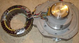
and mounted the halls from underneath it (so the wiring will all be protected from the rotor, and so that the halls will be closer to the air circulation from the baseplate/rotor gap--right next to it, in fact).
To keep them clear of the rotor, but without doing anything to the stator lams, I notched the filler sticks between the teeth instead, and superglued the halls to those (I didn't want to use epoxy yet, as I didn't even know if they would work there, plus I have no epoxy that would hold up better than superglue anyway).
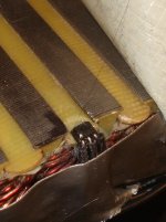
Naturally, it can't all go right. I managed to break a leg off the yellow hall while holding it and it's wires down while the glue set.
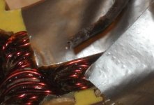
I did manage to fix it, after over an hour's dinking around with magnifying glasses, several flashlights and other lights to help me see, scraping plastic off the case away from the remainder of the leg (not even a quarter of a millimeter!), and several tries with the tiniest soldering tip I have. Eventually I got the leg glued down first and then soldered with a glob of solder to the hall. It's the output pin, so I'll know pretty well when it comes off again later.
All the duct tape came off after I got the wires all secured down (dots of superglue here and there to the stator endplates; they won't stay glued but will hold long enough for assembly) and halls glued in place. That was at least an hour and a half to hold wires while glue set (tape ripped them loose when removed, so had to hold by hand utnil set).
I had to take it apart twice because of pinched wires, as I didn't move them all out of the way of the baseplate's riser edge, apparently, and ended up with continuity from power and ground to the baseplate.
This is the EVAssemble "36V" 12FET I used to test it with, and it works well enough, though the red LED on the PCB flashes all the time it's powered on (can see it thru the end of the case for the wires, which I don't have screwed down). I bolted it tot he motor with the bottom motor baseplate screw, thru the end plate of the controller. Can't quite do what I planned and bolt it diagonally across the baseplate, because the phase wires are a cm or so too short.
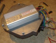
The phases are bullet-style, female, so I just removed the thick plastic housings that wouldnt' fit in teh D-style motor connector, wrapped the bullets in electrical tape to prevent accidental contact, and plugged the bullets onto the large round phase connector pins in the D-connector.
The motor hall wires I just tinned the ends of and stuck them into the female contacts of teh controller's white hall connector.
The whole test setup, using the Sorenson DCS 55-55 at 40V, 10A current limit, to simulate my 36V NiMH pack that isnt' currently charged up enough to use for the test.
View attachment 2
Scope is setup with a Phase (blue) on top at 10x / 2V/cm, and a hall (blue) on the bottom at 1x 2V/cm. I forget what the time setting was at. WattsUp from AussieJester used to monitor power usage.
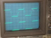
It took one full set of hall combinations (6) and then one phase swap and then 3 more hall combinations to find a smooth low-current no-load spin condition, at about 1.6A no-load current full throttle at 40V.
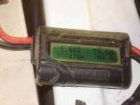
Ended up with Y-G-B on the phases on the motor connector, and G-B-Y on the halls. (in case I forget later)
Video of operation at 40V:
[youtube]D8JF2oVE6tk[/youtube]
Later I took it up to nearly 56V, which is as high as the Sorenson will go, and also as high as I think I should go on the 12FET.
[youtube]HlrXRX8fIKI[/youtube]
But it does work, on a cheapy type of ebike controller, at least at no load. I'll have to bolt the baseplate to something and try loading down the motor, probably via friction to CrazyBike2's front motor wheel in regen mode to a depleted battery.
If it still works ok, maybe I can mount it on CrazyBIke2 in the center frame, bolt a chainring to the face of the rotor, and connect it up to the chainline, and see what breaks first. :lol:
kfong
100 kW
Looking good AW, sounds like you now have a very powerful motor for your bike. Looking forward to the final build.
"Final build" :lol: That could be a while! Eventually this thing will go in the new bike, at least as a test motor, running the wheel via the NuVinci hub with autoshifter. Hopefully, at least. 
A few minutes digging htru the chainring pile finds only two that can easily be made to fit: Shimano I24 and I34. Dunno if I even ever had the 44.
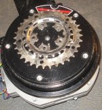
Most likely I'd use the smallest ring, and up the voltage, but I don't actually know what speed the motor goes at a particular voltage (kV) yet. I'll probably setup a speedo on it and find out soonish.
Either way, you can see that hte bolt holes don't quite line up, but I shoulc be albe to drill into them if I can borrow a friend's drill press. Either that or use my round file and lots of elbow grease, to lengthen each hole in the outward radial direction about half again their current size.
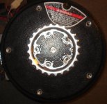
But I will need new bolts, as the existing ones are a bit short:
View attachment 2
I might have some that are long enough but I am not sure they're the same thread pitch. Have to find them and see.
I also found a bracket that coincidentally has teh same bolt hole width as one side of the rear mounting plate:
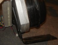
It's that computer-chair bracket (went between back of chair and base of seat) that I was planning on cutting up for the swingarm pivot plates on the bike this motor may go on.
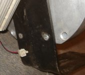
Too bad it's not exactly 90 degrees, or it'd be easy-peasy to mount up. I'll have to shim it up at the bend portion, or something, probably, if I use it (which I probably will because it does fit and is very thick and strong).
A few minutes digging htru the chainring pile finds only two that can easily be made to fit: Shimano I24 and I34. Dunno if I even ever had the 44.

Most likely I'd use the smallest ring, and up the voltage, but I don't actually know what speed the motor goes at a particular voltage (kV) yet. I'll probably setup a speedo on it and find out soonish.
Either way, you can see that hte bolt holes don't quite line up, but I shoulc be albe to drill into them if I can borrow a friend's drill press. Either that or use my round file and lots of elbow grease, to lengthen each hole in the outward radial direction about half again their current size.

But I will need new bolts, as the existing ones are a bit short:
View attachment 2
I might have some that are long enough but I am not sure they're the same thread pitch. Have to find them and see.
I also found a bracket that coincidentally has teh same bolt hole width as one side of the rear mounting plate:

It's that computer-chair bracket (went between back of chair and base of seat) that I was planning on cutting up for the swingarm pivot plates on the bike this motor may go on.

Too bad it's not exactly 90 degrees, or it'd be easy-peasy to mount up. I'll have to shim it up at the bend portion, or something, probably, if I use it (which I probably will because it does fit and is very thick and strong).
Some thoughts on RPM measurements:
A friend has a tachometer he can bring over to actually measure it easily, but I am still pondering other ways to measure or calculate it.
I was thinking I could measure it's RPM by friction driving the front wheel of CB2 and calculating what it would have to be to drive CB2's wheel at whatever speed shows up on the CycleAnalyst. Or by putting the speedo sensor on the motor directly with a magnet stuck to the hub's outer diameter (which I plan to do tonight anyway), and figuring out what the math would be to turn that into RPM.
I was also thinking that I should be able to calculate something close to it's actual RPM by knowing the speed at which it would have driven a powerchair at 24V. I presume it would be either 4MPH or 8MPH; I think I was told once but I forgot.
Another thought on RPM measurement is to just put a frequency counter on one of the hall signals, and divide by the number of magnets (40) or maybe that would be by the number of pole-changes (20) or maybe I am just lost.
Harold in CR
100 kW
Do you happen to have a Dremel tool ?? Drifting those sprocket holes would be MUCH easier with a Dremel. Drilling is going to be tough and probably end up snapping the bit. I have a cross feed vise I use on my drill press, and, HSS or Carbide die makers bits I can use for harder stuff. I made both sprockets from saw blade material using the Dewalt side grinder and Dremel for finishing work.
Good to see that motor spinning. You Da MAN. 8) 8)
Good to see that motor spinning. You Da MAN. 8) 8)
I have a dremel (the nearly-three-decade-old original variable speed version), but not any bits to use on that kind of work. I have a couple of cutoff wheels left, and some light sanding drums, and some small wood/plastic-working bits. Nothing that will handle metal like that.
I have a much larger (and older) similar tool with no speed control, but the bits I ahve for it for grinding are too large for the holes I need to enlarge.
So ATM it's either a friend's drill press, or a round file by hand.
I have a much larger (and older) similar tool with no speed control, but the bits I ahve for it for grinding are too large for the holes I need to enlarge.
So ATM it's either a friend's drill press, or a round file by hand.
With an eye towards possibly improving the motor's efficiency or performance with the halls and ebike controller, I've posted over here:
http://www.endless-sphere.com/forums/viewtopic.php?p=505649#p505649
in the "adding hall sensors to outrunners" thread, which I'd forgotten existed before I started this project. To keep this thread updated, I've quoted it below.
http://www.endless-sphere.com/forums/viewtopic.php?p=505649#p505649
in the "adding hall sensors to outrunners" thread, which I'd forgotten existed before I started this project. To keep this thread updated, I've quoted it below.
amberwolf said:I wish I had remembered this thread existed before embarking on my latest motor project...but now that I've re-found it...
I need to re-read this entire thread again (just finished reading it the first time now), but while I do that, and try to actually absorb some of the information that seems to be bouncing off right now, perhaps some input on my "project":
I've got a huge (20lbs+) brushless powerchair motor that's about the same size stator as something like the X5 series, I think, but it's wound to directly drive a small powerchair wheel (14", I think) at either 4 or 8MPH at 24V (really 28V, two SLA in series).
Built in it has SIN/COS analog sensor output...which is useless (without translation hardware) for ebike controllers (which is what I have avaialble to drive it). I added digital hall sensors at 120 degree physical intervals, gluing them temporarily with just superglue to hand-carved recesses in the material covering the windings between stator teeth.
It's a 45-tooth, 40-magnet, Wye-terminated motor. Presumably it is 15 poles? No idea on number of turns/etc, or inductance (yet, I have a plan to test that later once I find my signal generator).
Presently, the no-load full-throttle current at 40V is about 1.6A, and at 56V is about 1.7A.
There are pics and videos and further data in it's thread over here:
http://www.endless-sphere.com/forums/viewtopic.php?f=30&t=32838
if needed, or at request I can repost them over here in this thread.
What I would like to find out is what the optimum placement of sensors might be (for timing and high-load situations), if not where I already have them.
At present, there is definite clicking (of changing fields, not mechanical) at each part of a rotation equal to magnet passing stator tooth (or more than one tooth). That might simply be how it works with an ebike controller using trapezoidal commutation, and it might be smoother with a sine controller (but I don't have one). But if it can be made better by simple hall repositioning, I'm up for trying that, if anyone has a fairly certain idea of what might work better. I can't reposition them much, or I'll break the leads off (already did this to one and barely fixed it), and I have no spares except what is in other motors.
What I had planned was to install them on a ring on the outside of the mtor, but there isn't enough flux leakage for them to pick up, so they had to go inside on the stator.
There *is* another magnetic encoder source, which is the ring used for the analog SIN/COS output. I could probably mount them inside there where they can detect the domains on the ring, but I dont' yet know how many there are; if it's less than the number of magnets on the rotor, I'm not sure how things would work with an ebike controller.
Ok, so I scoped the hall rising-edge-to-rising-edge time at both minimum throttle and maximum throttle for 51.4V (present pack voltage on CrazyBike2, simpler and more comfortable than taking everything into the cold utility room to use the Sorenson).
I get 6.5ms for max throttle, and 140ms for minimum throttle.
If I multiply that times 20 magnets (40 total, 2 required for a full cycle), that's 121ms for a full rotation of the rotor. I forgot to measure the circumference of the rotor before I laid back down, so I'll have to do that another day.
But I know that the inside of the rotor at the magnets (where the halls are closest to) is about 171mm, maybe 172mm, because a 170mm disc brake rotor fits just about exactly in that space, with a tiny gap (see pic on a previous page). I'll go with 170mm because that's probably what the hall faces are at.
AFAICR, circumference = pi * (r*r), so that would be 3.1415 * (85*85), or 3.1415 * 7225 = 22697.3375, which should still be in mm. Apparently I must ahve the calculation wrong, because that comes out to 2.27meters, whcih is a bit over 74 feet! Off to google I go to find the *actual* formula for circumference.
Ok, so I was remembering the AREA formula, rather than circumference. What I needed was instead diameter * pi,
or 170 * 3.1415 = 534.055mm, which sounds a lot more reasonable, as that is 21 inches. Still sounds too big, though it could be right. I guess I'll find out when I actually measure it with a tape measure.
So, assuming 21 inches is right, then now to figure out how to turn 21 inches and 121ms into an RPM. If it takes 121ms to move 21 inches, then let's see....60 seconds in a minute, divided by 0.121s, equals...wait. I don't need the circumference to figure out RPM; I just need to know how many times 0.121s fits into 60s. That would be 495.87, so it should be roughtly 496RPM?
Then knowing how large the circumference is, I can translate that into MPH, right? First, 496RPM * 3600 (seconds in an hour) = 29760RPH. Each rotation is 21 inches, (well, at the halls), and there are about 63360 inches in a mile, so 63360 / 21 is 3017. 29760RPH / 3017 is 9.86MPH. That's at a diameter of 170mm.
The original wheels on the powerchair would be 14" diameter, I think, so going back to diameter * pi, I get 43.98, close enough to 44" circumference. so 63360 / 44 = 1440. 29760RPH / 1440 = 20.67MPH. That's a pretty fast powerchair. :lol: That is of course an unloaded RPM ti's all based on, so even if we take that to an assumption of 80% of unloaded for a typical loaded cruising speed, a 14" wheel gets us 16.5MPH. Still pretty good, considering it's direct drive!
So, now, let's see what a 20", 24" and a 26" bike wheel would get:
20": 20 * 3.1415 = 62.83". 63360 / 62.83" = 1008.44. 29760RPH / 1008.44 = 29.51MPH! Even unloaded, that's fast! Loaded 80% speed would be 23.6MPH. Faster than I need already.
So a 24" would be even faster, and a 26" would probably be way way too fast.
I'm tempted now to not make a chain drive with it, but just figure out how to bolt a bicycle hub to it and drive it directly. :lol: I could use a disc brake wheel, and make a plate that connects the brake bolts to the rotor's outer mounting hole ring. There'd be no hub axle needed, so it can be left out--this motor would do all the rotation and support. Tempting, but all I have are front hubs for disc brake bolt-on style. I'd have no pedal drive with that. Still, for an experiment, it might be ok. Leave the front hubmotor on there to get home on if I blow the controller on the rear. Make a big plate and arm to bolt the motor to that then bolts to my cargo frame and bike frame or something. Have to draw it up and see if I have the stuff to make it from.
Alternately, I coudl botl it to the disc brake that's on the big Suzuki dirtbike wheel....but that wheel is very large, with a 19" (IIRC) diameter rim, plus at least 4-6" of tire on top of that. And I only have a big knobby on there, so it'd be likely a bumpy (or vibratey) ride. Still...the way that would look, outrageously overdone, is even more tempting. :lol:
As a side note, in trying to determine actual phase voltage at speed, to see what the kV might be:
At max throttle I can't see any PWM going on in the motor waveform, but it's hard to tell since I can't reliably trigger on anything when time is zoomed in far enough to see, and I can't scroll the view to see much more than a bit of the phase when zoomed in enough to really see what might be PWM slices.
I can clearly see the PWM even with one complete waveform on teh scope, when at say, half throttle, but it gets a lot harder to see above that. Might show up on camera better, but I didn't set it up to take a pic. Maybe do that another day.
One reason it's hard to see is that it "jiggles", because the rotor itself appears to be off-center somehow, though I am pretty sure there's no way to mount it off-center, with the way the hub of the shaft fits to the rotor itself. That's actually part of the sound you can hear in the previous motor vids, getting faster with the higher motor RPM.
It actually causes a change in speed during each rotation, so that like a planet in an elliptical orbit around the sun, it goes gradually faster for half of the cycle, then gradually slower. This is visible in teh hall cycle length, which changes approximately 0.1ms over a full rotation at full throttle (possibly less).
I'm not up to taking the rotor off and seeing if installing it aligned with different boltholes on the hub vs the rotor will fix it, but I might try that another day.
I get 6.5ms for max throttle, and 140ms for minimum throttle.
If I multiply that times 20 magnets (40 total, 2 required for a full cycle), that's 121ms for a full rotation of the rotor. I forgot to measure the circumference of the rotor before I laid back down, so I'll have to do that another day.
But I know that the inside of the rotor at the magnets (where the halls are closest to) is about 171mm, maybe 172mm, because a 170mm disc brake rotor fits just about exactly in that space, with a tiny gap (see pic on a previous page). I'll go with 170mm because that's probably what the hall faces are at.
AFAICR, circumference = pi * (r*r), so that would be 3.1415 * (85*85), or 3.1415 * 7225 = 22697.3375, which should still be in mm. Apparently I must ahve the calculation wrong, because that comes out to 2.27meters, whcih is a bit over 74 feet! Off to google I go to find the *actual* formula for circumference.
Ok, so I was remembering the AREA formula, rather than circumference.
or 170 * 3.1415 = 534.055mm, which sounds a lot more reasonable, as that is 21 inches. Still sounds too big, though it could be right. I guess I'll find out when I actually measure it with a tape measure.
So, assuming 21 inches is right, then now to figure out how to turn 21 inches and 121ms into an RPM. If it takes 121ms to move 21 inches, then let's see....60 seconds in a minute, divided by 0.121s, equals...wait. I don't need the circumference to figure out RPM; I just need to know how many times 0.121s fits into 60s. That would be 495.87, so it should be roughtly 496RPM?
Then knowing how large the circumference is, I can translate that into MPH, right? First, 496RPM * 3600 (seconds in an hour) = 29760RPH. Each rotation is 21 inches, (well, at the halls), and there are about 63360 inches in a mile, so 63360 / 21 is 3017. 29760RPH / 3017 is 9.86MPH. That's at a diameter of 170mm.
The original wheels on the powerchair would be 14" diameter, I think, so going back to diameter * pi, I get 43.98, close enough to 44" circumference. so 63360 / 44 = 1440. 29760RPH / 1440 = 20.67MPH. That's a pretty fast powerchair. :lol: That is of course an unloaded RPM ti's all based on, so even if we take that to an assumption of 80% of unloaded for a typical loaded cruising speed, a 14" wheel gets us 16.5MPH. Still pretty good, considering it's direct drive!
So, now, let's see what a 20", 24" and a 26" bike wheel would get:
20": 20 * 3.1415 = 62.83". 63360 / 62.83" = 1008.44. 29760RPH / 1008.44 = 29.51MPH! Even unloaded, that's fast! Loaded 80% speed would be 23.6MPH. Faster than I need already.
So a 24" would be even faster, and a 26" would probably be way way too fast.
I'm tempted now to not make a chain drive with it, but just figure out how to bolt a bicycle hub to it and drive it directly. :lol: I could use a disc brake wheel, and make a plate that connects the brake bolts to the rotor's outer mounting hole ring. There'd be no hub axle needed, so it can be left out--this motor would do all the rotation and support. Tempting, but all I have are front hubs for disc brake bolt-on style. I'd have no pedal drive with that. Still, for an experiment, it might be ok. Leave the front hubmotor on there to get home on if I blow the controller on the rear. Make a big plate and arm to bolt the motor to that then bolts to my cargo frame and bike frame or something. Have to draw it up and see if I have the stuff to make it from.
Alternately, I coudl botl it to the disc brake that's on the big Suzuki dirtbike wheel....but that wheel is very large, with a 19" (IIRC) diameter rim, plus at least 4-6" of tire on top of that. And I only have a big knobby on there, so it'd be likely a bumpy (or vibratey) ride. Still...the way that would look, outrageously overdone, is even more tempting. :lol:
As a side note, in trying to determine actual phase voltage at speed, to see what the kV might be:
At max throttle I can't see any PWM going on in the motor waveform, but it's hard to tell since I can't reliably trigger on anything when time is zoomed in far enough to see, and I can't scroll the view to see much more than a bit of the phase when zoomed in enough to really see what might be PWM slices.
I can clearly see the PWM even with one complete waveform on teh scope, when at say, half throttle, but it gets a lot harder to see above that. Might show up on camera better, but I didn't set it up to take a pic. Maybe do that another day.
One reason it's hard to see is that it "jiggles", because the rotor itself appears to be off-center somehow, though I am pretty sure there's no way to mount it off-center, with the way the hub of the shaft fits to the rotor itself. That's actually part of the sound you can hear in the previous motor vids, getting faster with the higher motor RPM.
It actually causes a change in speed during each rotation, so that like a planet in an elliptical orbit around the sun, it goes gradually faster for half of the cycle, then gradually slower. This is visible in teh hall cycle length, which changes approximately 0.1ms over a full rotation at full throttle (possibly less).
I'm not up to taking the rotor off and seeing if installing it aligned with different boltholes on the hub vs the rotor will fix it, but I might try that another day.
Can't get the disc rotor bolts loose. Are soaking with oil on both ends overnight, hoping it'll help.
Got the front wheel's disc off, so I can use that as a bolt-pattern for making a disc that will mount to both the motor's face and the disc holes on the rear wheel, if I can get the brake rotor off the rear.
If I can't, I may just try it with the larger front wheel, but I'd rather use the smallest wheel I can for the test. Was considering actually using a 14" powerchair wheel, but the ones I have arent' for this bolt pattern/motor; they're for the older brushed motors.
Came up with a basic mounting arm idea, but cant' find the sketch I made of it at lunch today. so here is a terrible MSPaint versin.
deVries
100 kW
Just found this thread, and I was wondering about using Burtie's optical sensor timing tool instead of halls?
Just an afterthought I know, but maybe as a backup plan?

Just an afterthought I know, but maybe as a backup plan?
I considered optical sensors for a few minutes way back at the beginning, but halls were easier (at least, in the original plan :lol .
.
I would also have had to build whatever was needed, since I couldn't have bought anything to do it; I do already have IR LEDs and IR transistors, originally acquired for IR interconnect of my speedo sensor and PDA with Veloace, back in the first DayGlo Avenger lighting and electronics setups before even successfully motorizing it.
The electronics would've been a bit more complicated just to use the optical sensors, too, with added resistors and possible waveshaping transistors after the IR transistors.
The nice thing would be that to adjust timing, I would jsut have to move the light/dark bands on the rotor clockwise or counterclockwise a bit, but it was more work overall than I wanted to do just to try it out. It is still possible I might go that way.
However, Mdd0127 has volunteered a Timing Adjuster (from Burtie) to play around with timing to see if it does make any difference to adjust it, without disassembling the motor and moving the halls around to try it out. Then, if it does help, I can simply move them to the final position once I've figured that out.
I still have to hook the motor up to a good load first, to be able to see if it will even operate correctly that way; it's easily possible that it won't or that I'll blow up the controller. :lol: Right now the plan is to go to a friend's shop today and see if we can drill out a disc brake rotor for slightly larger holes, and then make some spacers so I can bolt it to first the wheel (a 24" disc-brake front) and then to the motor. Once that's done, I can build a small frame to bolt the motor to the back of CrazyBike2 or some other bike, something like the drawing in a previous post, and then see if it will drive the bike.
If it will work as direct-drive, then I know for sure it will work as chain-drive, and can work that out later (because chaindrive is more complicated and more likely to have failures unrelated to the motor itself, which is why I ended up putting the hubmotor on CrazyBike2 in the first place, even though I prefer shiftable chain drive).
We tried to drill out the holes, but ended up only dulling his bits before we got all the way thru it.  I don't know what kind of bits they were, other than darker gray/black colored. Apparently not good enough for stainless steel, anyway.
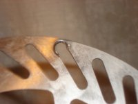
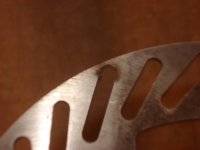
I'm going to dig out the round files and see how far I get with that. Might not be too slow on the mostly-done one, but there's four more I didn't even get to start, plus the six small mounting holes in the center must be expanded inward to fit the ISO BCD holes on my hub. Then I have to make the spacers to hold the motor and disc tight but not bending the disc.
This would be lots easier if I had a big enough sheet of normal steel, maybe 1/8"-1/4" thick, or aluminum at least that thick. I'm just glad I have *something* that does fit; this is just for a basic test and wont' be the final setup, anyway.
This is about what it will be positioned like when it's done. You can see the ends of 5 of the slots end right over the centers of the 5 rim bolts, which I thought would make this all "easy".
View attachment 2
The disc by itself, with the partial hole:
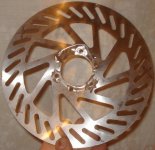
I also took the two known-good Zippy 5s packs from Mdd0127 and built them into a 10s to use to test this motor with, so I don't have to keep dragging it to the Sorenson to use, or unhook CrazyBike2's pack to test this with it.
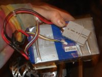


I'm going to dig out the round files and see how far I get with that. Might not be too slow on the mostly-done one, but there's four more I didn't even get to start, plus the six small mounting holes in the center must be expanded inward to fit the ISO BCD holes on my hub.
This would be lots easier if I had a big enough sheet of normal steel, maybe 1/8"-1/4" thick, or aluminum at least that thick. I'm just glad I have *something* that does fit; this is just for a basic test and wont' be the final setup, anyway.
This is about what it will be positioned like when it's done. You can see the ends of 5 of the slots end right over the centers of the 5 rim bolts, which I thought would make this all "easy".
View attachment 2
The disc by itself, with the partial hole:

I also took the two known-good Zippy 5s packs from Mdd0127 and built them into a 10s to use to test this motor with, so I don't have to keep dragging it to the Sorenson to use, or unhook CrazyBike2's pack to test this with it.

Alan B
100 GW
Stainless work hardens easily, need the right drill bit, lubricant, and speed. Probably work hardened and dulled the drill bit.
Farfle
100 kW
Alan B said:Stainless work hardens easily, need the right drill bit, lubricant, and speed. Probably work hardened and dulled the drill bit.
Yup, the SS work hardens faster than the bit, so cut slow, and use lots of lube and it works just fine with any sharp drill bit, even the HF ones. Biggest thing is to just go slow, the enemy is heat.
Similar threads
- Replies
- 3
- Views
- 1,467
- Replies
- 1
- Views
- 1,385
- Solved
- Replies
- 13
- Views
- 900


