tahustvedt
10 kW
Feels like information overload. ")
Is a buck converter all I need? I can buy a DC-DC boost converter and connect to the charge port of the BMS. Not sure if it will add energy simultaneously with draining the battery. I think the BMS prevents that. Maybe I can add a relay which connects it to the battery output when I ride, and the BMS charge port when the velo battery is switched off.
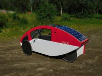
I wonder how Organic Transit solar charging works.
Is a buck converter all I need? I can buy a DC-DC boost converter and connect to the charge port of the BMS. Not sure if it will add energy simultaneously with draining the battery. I think the BMS prevents that. Maybe I can add a relay which connects it to the battery output when I ride, and the BMS charge port when the velo battery is switched off.
I wonder how Organic Transit solar charging works.