Dear all,
I have received an old classic line (2013, I think) Bosch mid drive motor unit. The battery of the bike is not present. I would like to use this mid drive in a future bike build, but I am aware that these systems are built heavily integrated, so that only Bosch parts can be used for things to work. I would therefore like to convert the motor software or hardware to be more accessible. I have considered re-designing the PCB, but would rather attempt to re-program the microcontroller first. Before I dive into this project, I would like to get an estimation of the difficulty and overall plausibility of this plan.
1. Does it seem plausible to re-program the microcontroller with adapted open source (sensorless) BLDC control software (such as presented here: https://endless-sphere.com/forums/viewtopic.php?f=30&t=36479)?
2. Would there be other individuals that would be interested in the know-how of such a conversion, so that I know I am not doing this just for this project, but rather helping others on the way as well?
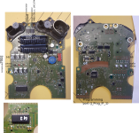
I have started reverse-engineering the PCB in the motor, see the schematics in the attachment (not completed). I have focused on the motor drive rather than sensor readout. I am not very worried about the display functionality at the moment, it is not of highest priority.
Thanks in advance for your advice,
Bart
Some technical details:
The BLDC sensorless motor is switched by 034N06 FETs, driven by an MC33937 FET driver, which is controlled by a STM8AF52A9TC microcontroller (24 MHz, 128 kB flash, 6 kB RAM, 2048 B EEPROM. See more information here: https://www.st.com/en/microcontrollers-microprocessors/stm8af52a9.html.
The PCB is a 3+ layer board, partially covered in a conductive epoxy (where the board is close to the gearwheels).


