Rectifier Huawei R4850G2 48V 42~58V 3000w

Has anyone tried higher voltage on these psus? I set it to 55v yesterday and it was getting a lot warmer then on 48v. Is that normal, Is it ok to run it at around 50c surface temp? I have it in an enclosed box to dampen the fan noise and at 48v it was basically room temp after running a few hours but at 55v it got quiet warm after a few hours.
Mine is modified and 0-100v but it can be 70c no problem working there for some hours. Max charge length for me is about 2-3 hours. If I can and do a mod I would add a fan onto it.

When you place the charger. Don't put a pillow on it if you get the point.
 
Guys, been using a R4875G5 for a while now on my custom 14kw battery "supplimental" system that is charged for literally free during free hours of 8pm to 6am, and then running house on entirelly the battery fed in with rapid shutdown Micros that can output about 3.6kw cpontinues (enough to run the house and AC no problem). During peak sun, I do recharge the batteries as well with solar feeeding in. So far, daily paid usage been averaging 300 watt/day of paid import. So cant complain.
The charging has been done via the 4875 and it worked great over can (rapid voltage adjustemnts for solar charging and nice steady 40amp charing at night). Have external fan on the unit as well to suppliment cooling and seems it stays around 40-55c constantly.
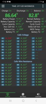
However, few days ago ran into some strange issue. (last 6 months had not a single issue what so ever and was maintenance/support free). Noticed that system was charging on and off like charge for 1 minute at 40amp, then off for 30 seconds and back on. Went out, reset everything just to be safe, and same issue. When the system is not charging during those waves, I hear a click from PS right before it shuts down and then see solid red light. Then it "recovers and starts charging again for a minte or so. If I set teh charging to 25amps, zero issues nad it charges all night long. Second I ge to 30 and above, same issue continues. I did monitor the voltage at BMS and it never jumps or goes up that I can see to warrant over-voltage (red light seems to mean overvoltage from the user manual). Anyone seen any similar behaviors from these units?
 
With your external fan, you reduce the fan speed from the internal fan, probably now other components inside that are only air cooled get to hot.
Solid red is no good sign.

Screenshot_20241027_174923_Drive.jpg
 
Last edited:
Internal fan always sounded/sounds like its fully running once im at 30+ amps. Also the external fan is part of the body now positioned right in the middle of the body and has airflow about 3 times the internal fan. There is a chance its actually outflowing the original fan and pushing air backwards through it. I did IR reading on the components when I first built it it and with external fan I saw about 30% temp drop throughout every big component I could get a picture of.
Also this setup worked Perfectly charging at over 95F ambient 5+ hours (texas summer) and temps never got over 55/60c while stock fan couldnt keep it cooled for prolongued time at those ambient temps. I might be wronog but dont Think its temp related. Also part of my code is to first throttle back reported temps and then cool down for 10 min if we touch 60.
 
The internal fan does not even spin full at 80A and 35C / 95F.
But if you checked with an IR cam then you are probably right that it is not temperature related.

I use them for charging my 7,7kwh scooter battery.
 

Attachments

  • 20231017_175406.jpg
    20231017_175406.jpg
    1.4 MB · Views: 37
  • Screenshot_20231017_175314_Serial Bluetooth Terminal.jpg
    Screenshot_20231017_175314_Serial Bluetooth Terminal.jpg
    871.1 KB · Views: 38
  • Screenshot_20231017_175055.jpg
    Screenshot_20231017_175055.jpg
    748.1 KB · Views: 37
Last edited:
Thanks will give that a try. However yesterday I limited the charging to 25amp in the code. Once the free time came, it started to charge, charged for few minutes, and then went back to some weird state. The charging dc reported limit fell to 17.3amp with 0amp flowing out, fan on slow speed, No red lights just single green this time, and unit making clicking noises. Shut it down via can with dc/ac still love, waited a minute, requested to turn on again. Still clicking with no output. 20 seconds later goes to 25amp and zero interruptions all night charging 12kwh.
 
Some fresh esp32 ESPHome YAML code to control one or more of the rather "silent" R4875G1 variant on Github:
with some hardware advice. This software is also compatible with R4850G2.
 
Last edited:
hi guys,

come back to know if someone had the problem, my secondary don't exceed 10a and isn't stable even i try to set voltage by can bus, it s waving from 7v to 10.6v, so i think something is burnt , any idea of witch one

best regards,
 

Attachments

  • IMG_20241205_003059[1].jpg
    IMG_20241205_003059[1].jpg
    11.9 MB · Views: 28
Try measuring the output with your meter in AC volts mode. This will tell you if your output caps are bad. Normally this should be very low, like millivolts. If the caps are bad you'll see more than a volt AC.
 
Mine is modified and 0-100v but it can be 70c no problem working there for some hours. Max charge length for me is about 2-3 hours. If I can and do a mod I would add a fan onto it.

When you place the charger. Don't put a pillow on it if you get the point.
Could you share your experience in modifying the power supply? I think your contribution to this matter could be appreciated here
 
Could you share your experience in modifying the power supply? I think your contribution to this matter could be appreciated here
I haven't modified my controller but bought it ready-made. It broke one time and I just put a new fuse and wires on and was lucky to have it working thereafter.

My wish forward when I get time is to check output voltage för ripples if its within normal limits or not.

I have bought another unit for cheap which I will try to repair and se if I can get it running. Basically checking a few wires, fuse and measure some points.

I have secondary thoughts that it may be an issue with my unit but it may also be my old cells acting up. I have Panasonic PF cells and they get hit by 2-5A each maximum but some brake their internal fuse or acts. When writing this I got an idéa that I may have gotten bad or oddly used cells which is acting up one after another in my battery pack. Thanks for asking me. I will write again here when I got time to open up that other power supply.
 
These units are designed for round-the-clock operation, without shutting down. The battery is discharged, not the capacitors, but the dc/dc converter on the control board. The voltage from the output is supplied to it in parallel with the standby voltage through a diode. It is possible to remove the diode, but you are unlikely to be able to do it.
View attachment 328565
View attachment 328566

Hello,
I have a different PCB layout and can´t figure out where to get 5V to supply an ESP32 for CAN control.
I tried differnt spots where I measured 5V (or 3.3V) but when I connect the ESP it drops to about 1V.
Anyone a hint for me?
Thank you and Best Regards,
Daniel
IMG_20250406_125826.jpg
 
Most of the electronics inside ought to be powered from 5v. Most chips will probably have bypass capacitors next to their supply pins, and you should be able to tap 5v from that, unless the PSU you have is designed with such a marginal 5v regulator design that can just barely supply enough current to run the PSU's internals, so when you add your ESP32 load it shuts down.
 
I added a small dc/dc for the esp32 and took power from the 12V rail in my r4875g5
 
Back
Top