justAddElectrons
10 µW
- Joined
- Jan 26, 2022
- Messages
- 5
I read through a ton of "speed controller" and related posts, also posts including "Arduino" but couldn't find an answer to my questions, so...
I just took apart an old "Scooter One 2020". There was no battery but otherwise I think it could have been functional. I got it from someone for $10. It was their kid's and it was totally beat up. That's all I know about it. It has a mechanical (cable) rear disk brake.
I'm interested in repurposing the hub motor, e.g. as maybe a robot actuator or drive wheel or a spindle motor or just whatever gadget I make that needs motion.
I am not that familiar with e-scooter controllers although I have some experience with electronics, motors and prototyping in general.
My confusion is to how to repurpose the controller and what some of the wires are for and how to give them signals. I don't want to use the dashboard but instead control the speed controller and motor via either Arduino or Raspberry pi. That said, I will try first to see if I can get the motor to spin with the existing dashboard and throttle.
Of the 9 connectors coming out of the speed controller:
- The three phase connectors are clear.
- The hall sensor connector is clear.
- The battery power connector is clear.
What remains are 4 other connectors:
1) one with 4 wires goes to the dashboard.
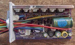
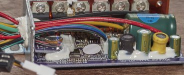
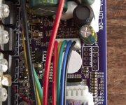
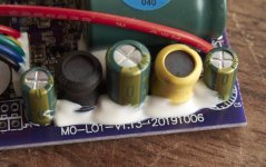
2) two black connectors, both with two wires, both connected on the same mini add-on pcb inside the controller (see pics). No idea what they're for.
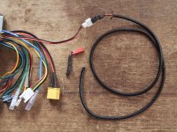
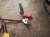
3) one white one with two wires, no idea what it's for and couldn't really tell where it was connected on the PCB unfortunately. But it was connected to a cable going to the back end of the scooter. I wasn't really paying attention while disassembling. I don't think there was a light there but it might have broken off. There was a lot of damage to the scooter.
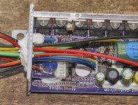
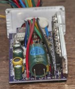
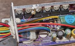
Below are pictures that show the controller in detail. Also one picture of the dashboard.
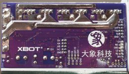
The controller says "XBOT" on the PCB as well as "MO-LO1-v1.13-20191006" (not sure that's M-zero or M-oh, ditto for LO). I couldn't find any references for ""MO-LO1-v1.13" and variations thereof.
The dashboard PCB is marked "MO-2BLE1-V2.01 20181026".
The black felt marker text on the outside, "ONE2020112746" I wrote for future reference for myself.
I found only a couple of references for the dashboard "MO-2BLE1-V2.01 20181026":
Anyone...iScooter info - ScooterHacking.org
https://rollerplausch.com/threads/midu-flasher-st-link-downgrade-unbrick.5399/page-22
but I suspect it's a commonly cloned one like
https://www.amazon.com.au/Scooter-Clone-Dashboard-Circuit-Replacement/dp/B08F27FDD6 ...although the devil might be in the details between versions of it that are close but not exactly similar.
So my questions are:
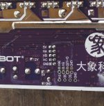
1. How do I communicate with the speed controller using an Arduino or Raspberry Pi? It looks like maybe the wires are connected to the PCB holes labeled 5V, GND, OFF and RX. Some kind of UART? But what speed and what commands? (I think TX is not connected externally).
2. What are the other connectors for?
3. Can I just ignore the other connectors or does the speed controller expect a certain signal from them in order to be enabled?
I know I could run the motor with a generic brushless controller w/ hall inputs and I have some of those on hand but I wouldn't mind using the speed controller that it came with in the scooter if possible.
In some of the pictures below where it's relevant, I put the connectors in the picture next to the pins where they were connected on the PCB.
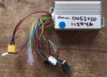
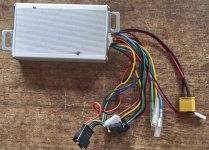
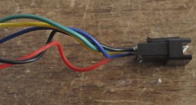
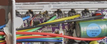
This must be for the display (c.f. pic below with front wheel and all the cables coming from the front handlebar tube).
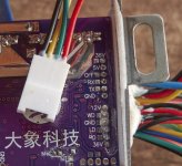
These black connectors appear to be connected to the little add-on PCB with the "QC PASS/3" sticker.
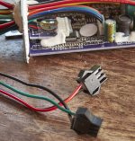
And that add-on PCB is connected to all or some of these labeled pins underneath: 12V, WD, GND, LD, RD, 36V
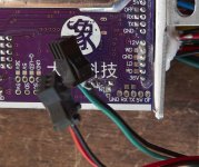
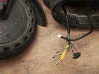
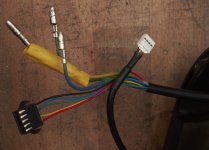
The connector to the cable going to the back end of the scooter. The far end of that cable had the red connector, pictured here completely detached because I had to cut it off to pull the cable out of a hole through a metal structure.
I just took apart an old "Scooter One 2020". There was no battery but otherwise I think it could have been functional. I got it from someone for $10. It was their kid's and it was totally beat up. That's all I know about it. It has a mechanical (cable) rear disk brake.
I'm interested in repurposing the hub motor, e.g. as maybe a robot actuator or drive wheel or a spindle motor or just whatever gadget I make that needs motion.
I am not that familiar with e-scooter controllers although I have some experience with electronics, motors and prototyping in general.
My confusion is to how to repurpose the controller and what some of the wires are for and how to give them signals. I don't want to use the dashboard but instead control the speed controller and motor via either Arduino or Raspberry pi. That said, I will try first to see if I can get the motor to spin with the existing dashboard and throttle.
Of the 9 connectors coming out of the speed controller:
- The three phase connectors are clear.
- The hall sensor connector is clear.
- The battery power connector is clear.
What remains are 4 other connectors:
1) one with 4 wires goes to the dashboard.
2) two black connectors, both with two wires, both connected on the same mini add-on pcb inside the controller (see pics). No idea what they're for.
3) one white one with two wires, no idea what it's for and couldn't really tell where it was connected on the PCB unfortunately. But it was connected to a cable going to the back end of the scooter. I wasn't really paying attention while disassembling. I don't think there was a light there but it might have broken off. There was a lot of damage to the scooter.
Below are pictures that show the controller in detail. Also one picture of the dashboard.
The controller says "XBOT" on the PCB as well as "MO-LO1-v1.13-20191006" (not sure that's M-zero or M-oh, ditto for LO). I couldn't find any references for ""MO-LO1-v1.13" and variations thereof.
The dashboard PCB is marked "MO-2BLE1-V2.01 20181026".
The black felt marker text on the outside, "ONE2020112746" I wrote for future reference for myself.
I found only a couple of references for the dashboard "MO-2BLE1-V2.01 20181026":
Anyone...iScooter info - ScooterHacking.org
https://rollerplausch.com/threads/midu-flasher-st-link-downgrade-unbrick.5399/page-22
but I suspect it's a commonly cloned one like
https://www.amazon.com.au/Scooter-Clone-Dashboard-Circuit-Replacement/dp/B08F27FDD6 ...although the devil might be in the details between versions of it that are close but not exactly similar.
So my questions are:
1. How do I communicate with the speed controller using an Arduino or Raspberry Pi? It looks like maybe the wires are connected to the PCB holes labeled 5V, GND, OFF and RX. Some kind of UART? But what speed and what commands? (I think TX is not connected externally).
2. What are the other connectors for?
3. Can I just ignore the other connectors or does the speed controller expect a certain signal from them in order to be enabled?
I know I could run the motor with a generic brushless controller w/ hall inputs and I have some of those on hand but I wouldn't mind using the speed controller that it came with in the scooter if possible.
In some of the pictures below where it's relevant, I put the connectors in the picture next to the pins where they were connected on the PCB.


This must be for the display (c.f. pic below with front wheel and all the cables coming from the front handlebar tube).

These black connectors appear to be connected to the little add-on PCB with the "QC PASS/3" sticker.

And that add-on PCB is connected to all or some of these labeled pins underneath: 12V, WD, GND, LD, RD, 36V


The connector to the cable going to the back end of the scooter. The far end of that cable had the red connector, pictured here completely detached because I had to cut it off to pull the cable out of a hole through a metal structure.


