Science, Physics, Math, & Myth

John in CR said:
it needs 200A while on for an RMS current of 100A. If that's true then the speed motor running the high voltage makes more heat with the shorter on time of higher current. eg 100A ON for a full cycle makes less heat than 200A ON for 1/2 cycle of PWM.

If I'm reading correctly then I think the answer is here:

liveforphysics said:
As the controller bucks, the current doesn't stop flowing when it's not switched on, it just flows from the coil's field collapsing back into the controller's mosfet body diode. The inductance of the motor does for current what a capacitor does for voltage, this keeps it essentially smooth and regular, even while the FET is pwm'ing at 20kHz or whatever, and the voltage waveform looks like a mess of ugly square waves (even on a sinus controller).

The motor windings don't see peak or RMS current in response to the PWM, rather the inductance of the windings converts the choppy current to DC. Therefore, current is constant while a particular phase is "on". Much like the individual cylinders in an ICE produce a series of rapid torque spikes, but the flywheel smooths this to a constant (almost) torque.

The battery side of the motor controller would see a choppy current waveform, hence the need for adequate capacitors.
 
Punx0r,
I appreciate that inductance rounds off the corners and smooths the peaks, but the faster the winding, the lower the inductance. I always viewed the battery having the easy side of the equation with the caps on the input side being necessary to counteract inductance in the battery and it's wiring, so it provides instant power as the controller requests it. I've definitely seen phase wires get hotter than battery wires of the same size, and the energy passed is put through 3 phases compared to the battery's 2 wires, which tells me actual current on the phase wires must be higher. Also, it's the phase side of mosfet banks that blows far more often, isn't it?
 
PWM frequencies are selected such that the current ripple will be small compared to the average current, so the current in the motor winding is essentially constant, it rises slightly during the PWM on cycle as energy is transferred from battery/capacitors to the motor's magnetic field, then during the PWM off period the current flows through an FET body diode as it decays slightly fed by energy from the shrinking motor magnetic field. But the current throughout this cycle is essentially constant.

Anytime the PWM is less than 100% the phase current will be larger than the battery current.

PWM rarely gets to 100%, even at WOT, especially with "fast wind" motors.

One way to think of it is the motor controller converts power from battery voltage to motor voltage, so power in equals power out (ignoring the relatively small losses). If the motor is low voltage, the current is higher, etc.
 
Alan B said:
PWM rarely gets to 100%, even at WOT, especially with "fast wind" motors.
If the controller works below battery amp limit at WOT, it must be at 100% PWM or block commutation (RMS phase voltage = battery voltage). I set my controllers battery amps always that high so it can reach 100% pwm pretty fast - even at very steep hills it stays there / get there after accelerating at wot!
Many RC controller stay always in block commutation at full throttle input, because they have no battery current limit (peak current depends on phase to phase resistance or whatever).
 
Your right, low powered systems are often set up to get near 100% PWM frequently, after acceleration. On a steep hill, if speed drops a lot, PWM likely comes back into play to prevent FET failure. The higher power the system is the more PWM must be used to control it as resistances are too low to do so.

Many controllers limit at about 99% PWM to make their gate charge circuits work. They cannot ever do 100% unless commutation is fast enough to recharge the gate drive circuits, or they have DC-DC converters to charge them (which most controllers don't have). On a hill, even though the battery current is within limits, PWM may come into play as the commutation rate falls, to charge the gate circuits.

Something must limit the current enough to prevent failure of the FETs, either the back EMF, system resistance or the PWM. This is why RC controllers fail so often, they depend on a close match between system voltage, back EMF, system resistance and loading to avoid destruction. An increase in load can cause the system to fail. The controller isn't really in good control.

Operating at near 100% PWM indicates there is no control left, every hill will slow the system down, there is no margin. It is not a particularly desirable situation for a vehicle.

On sine wave systems the PWM is used to make the sine waves, so it doesn't do near 100% except possibly on the moment of peak current, so most of the time it is not near 100%. Anything using a sine wave controller is not using near 100% PWM much at all, even at WOT.

Most non sinewave ebike controllers measure battery current and calculate an estimate of phase current, and they use these values to limit PWM. So even though the rider input calls for WOT (and even though the battery current is not at the limit) the controller cannot allow full PWM until the speed is high enough that back EMF and system resistance will limit the phase current and the commutation rate is high enough to charge the gate circuit. The higher power the system is, the lower the resistance, and the more PWM must be used to control it. Even if near 100% PWM is reached at full speed, every stop and start drops the PWM value for the deceleration and much of the acceleration period. Any time the commutation rate is low the PWM can't reach 100% to insure the gate circuits are charged. So the controller software considers a number of factors when calculating the PWM to use, not just the battery current.

Unfortunately controllers don't give us a readout of PWM so we don't really see all this happening, it just goes on under the hood.
 
Alan B said:
So even though the rider input calls for WOT (and even though the battery current is not at the limit) the controller cannot allow full PWM until the speed is high enough that back EMF and system resistance will limit the phase current and the commutation rate is high enough to charge the gate circuit.

im with you. i see it like this when accelerating with WOT from a dead stop:

first controller does limit phase current, second it limits battery current and third (no limits anymore) it switches to 100% PWM. When going up a hill it stays in 100% PWM until battery / or phase current limit kicks in again (with the common 1:2 or 1:3 batt to phase A settings its normally the battery current limit which turns the controller back in "bucking down mode").
 
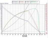
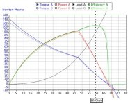
torque_V_turn_Count.PNG
liveforphysics said:
Kiwifiat- You are still failing to get it, perhaps at all levels. This seems astounding, as I don't believe you or Kingfish are incompetent to understand.

I^2*R loss is the copper loss component. If the same amount of copper is around the tooth, it makes the same amount of continuous torque, and continuous power, and the same heat production per amount of torque etc. Likewise, it would be no additional power consumption from a battery to make that same amount of torque/power etc.

A motors resistance climbs at the SQUARE of the number of turns, yet the current demand to make a given amount of torque varies inversely proportional, yet this linear decrease in current decreases heating by the ROOT of current. This makes them cancel each other cleanly, and is why a 1t motor makes torque exactly as efficiently as a 10t motor, despite one needing 10x higher drive current (at 1/10th the average bucked-down phase voltage, so power drawn from the pack is identical).

I was going to break it all down again for you in a long response, but I don't think it needs to be made clearer than the examples already provided in this thread, it just needs them to be read and understood rather than read and replaced by pre-existing confused delusions of knowing.

Liveforphysics I wonder if you even read and comprehend what others are saying. Above I wrote:
Kiwifiat said:
Niether Kingfish or I are debating the fact that copper losses between equal fill winding options are equal, the proof is trivial..

Can I make it any clearer?

You are whipping a dead horse on this point, there is no debate. I learnt that fact 32 years ago. Equally we can see that 10x1 = 1x10 , no debate and nothing insightful stating the bleeding obvious. What is obvious is that you have formed the opinion that you can drive however much current into a motor at any speed in order to convince yourself that turn count is irrelevant. Of course some of us have been taught that the amount of current that can be usefully driven into a motor is governed by the laws of physics as we know them.

We all know that the higher the turn count has a lower maximum rpm. We all know that we can convert Kv to Ke and that if we use SI units we also get Kt. So we can see that a higher turn count motor produces more torque per amp than a low turn count motor. We know that peak power is around 50% of the maximum no load speed and since the motors have different winds it follows that peak power occurs at different speeds. And since the power curves are different the torque curves must also be different. And if the power curves and the torque curves are different then the performance in a vehicle all else being equal will also be different. And we can see this without the use of a dyno, it is no more than the Laws of Physics tell us.

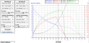
Attached above is a comparison from ebikes.ca of two more or less equal fill motors with the same constrained power source and controller fitted into the same diameter wheel.

What can we see? Well it seems that the higher turn count motor produces more torque all the way up to 40 Km/h, now I know you told me it is myth and BS but in my world more torque gives more tractive force at the wheel and according to Newtons Second Law of Motion that means better acceleration.

And as already stated by myself and others the higher turn count motor has a lower top speed, and as stated already the lower turn count motor has a higher top speed. And we can also see that both motors produce more or less the same power. Doesn't seem like the same real world performance does it.

And no surprise in my mind as that is exactly what the laws of physics predict.

liveforphysics said:
it just needs them to be read and understood rather than read and replaced by pre-existing confused delusions of knowing.

liveforphysics, you can belittle those with opinions that don't agree with your own. I was taught,verified in a laboratory, and examined on what I know about the subject at hand. There are no confused delusions in my mind.

I have read widely on the subject of motor design and I can not find a single reference to your opinion that a three phase motor inverter is a buck converter which seems to be the mysterious magic you bandy about whilst attempting to prove your point of view. So I ask again give us a reference to an IEEE paper or a PHD thesis to support your theory that you can drive any amount of current into a motor at any speed with a 1000V volt 10A inverter such that all motors regardless of inductance and resistance become equal. Until then we will just have to agree to disagree, but as James Mevey notes in his awesome thesis there is a lot of disagreement on the subject so we are in good company. :D
 
It would be best to check the personal attacks at the door, and keep the discussion technical.

Actually the usual ebike trapezoidal BLDC motor controller is three buck converters, or possibly six, depending on how you want to think of it, but the multiplicity doesn't add anything to the analogy, and in a six-step commutation process only one is active at a time.

A basic power supply type buck converter consists of an FET switch, an inductor, a diode, and a load.

The active portion of a BLDC controller for one PWM cycle consists of an FET switch, an inductor, a diode and the load is a voltage source the value of which is the back EMF of the motor.

So the BLDC controller is effectively a buck converter driving a load at varying voltage. Commutation switches around which coil is driven in which direction, but it is in each case a buck configuration.

In each case the FET switch conducts energy in from the power source (battery) to the inductor and load for the PWM on cycle, and for the PWM off cycle a diode conducts the circulating current generated by the collapsing magnetic field in the inductor. The energy stored in the inductor is converted into additional current that did not come from the power source.

A quick web search for "buck BLDC controller" produced over 100K hits, many of which show examples of the buck description of a BLDC motor controller:

http://www.sciencedirect.com/science/article/pii/S1000936113000897 this paper discusses using buck BLDC motor controllers, and the diagram matches the standard ebike controller layout

and so on.
 
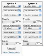
Kiwifiat, you are comparing two different motor winds with a fixed amperage controller at the same throttle. If you adjust the amps to 37.5 and the throttle to 67% for the 3004 motor the curves are almost identical. The throttle and amp amounts need to be adjusted by 4/6 and 6/4 respectively for an apples to apples comparison.
 
Kiwifiat,

Really???

That comparison isn't even apples and oranges. It's comparing watermelons and bananas.

This is the manner in which you compare those 2 motors for purposes of this discussion. Since the simulator includes the whole system, I changed battery and controller configs to be on par. The resulting small difference is due primarily to being unable to resize the phase wires, differences in copper fill (if any), and potential inaccuracies in the simulator itself.

NineC 3006 and 3004 a.JPG
View attachment 1
 
Allex said:
Seems like some of us like to use same throttle but different motors to get different results on the road.

I've followed most of your points, but this one makes no sense to me before even considering that without a change in controller settings you put the slow motor at greater risk of burning up if you had it tuned well for the fast motor. Assuming you can get virtually identical performance from the 2 motors at the same voltage (something I'm still not 100% sold on because I believe phase currents spike higher at the lower duty needed for the fast motor to produce the same rpm and torque as the slow motor than they would if run at a lower voltage), then why on earth would you swap the motor out when the same result as the slow wind with same throttle positions can be had by simply tuning a 3 speed switch and using it? Swap motor vs flip a switch, the choice seems clear.
 
When viewed at realistic continuous use and the same battery and phase power:
apples.jpg
apples2.jpg
 
I got questions and felt that this was the thread to post them on. First, I get it when copper fill is the same in motors with different winds being compared, the same thrust output potential can be achieved, given the amps and volts are adjusted for such as the example shows in John in CR's post the simulator. This is what I learned. When I originally swapped the 5403 on my Bomber for the 5404, I noticed a bit of an increase off the line WOT. 80v @72amp DC. This came at a price of lower top speed which was unassisted dropped form 53MPH to 46MPH. I expected this. Then when I got the 5405, it wasn't any faster off the line, and the top speed was 39MPH. Checking my CA data, even though I had DC amp limited to 75, the 5405 would only peak draw 67amps. So I contacted Kenny and learned that the copper fill on the 5404 is more than the 5403. The 5404 and 5403 both use the same diameter of copper wire, .083 thick. The 5404 has 4 turns vs the 5403 with 3 turns, so is it safe to assume that the potential for a stronger field can be generated with the 5404 due to higher copper content? As I learned, this is not the case with the 5404 and 5405 though. As I also learned, the 5404 has .083 thick copper wire with 4 turns on the wind, the 5405 has 5 turns, but is using thinner .065 copper wire. The copper fill is almost identical. So would I be wrong in assuming that the 5404 would perform identical to the 5405 if the amps were increased by 20% and the volts decreased by 20%.
 
Rix said:
I got questions and felt that this was the thread to post them on. First, I get it when copper fill is the same in motors with different winds being compared, the same thrust output potential can be achieved, given the amps and volts are adjusted for such as the example shows in John in CR's post the simulator. This is what I learned. When I originally swapped the 5403 on my Bomber for the 5404, I noticed a bit of an increase off the line WOT. 80v @72amp DC. This came at a price of lower top speed which was unassisted dropped form 53MPH to 46MPH. I expected this. Then when I got the 5405, it wasn't any faster off the line, and the top speed was 39MPH. Checking my CA data, even though I had DC amp limited to 75, the 5405 would only peak draw 67amps. So I contacted Kenny and learned that the copper fill on the 5404 is more than the 5403. The 5404 and 5403 both use the same diameter of copper wire, .083 thick. The 5404 has 4 turns vs the 5403 with 3 turns, so is it safe to assume that the potential for a stronger field can be generated with the 5404 due to higher copper content? As I learned, this is not the case with the 5404 and 5405 though. As I also learned, the 5404 has .083 thick copper wire with 4 turns on the wind, the 5405 has 5 turns, but is using thinner .065 copper wire. The copper fill is almost identical. So would I be wrong in assuming that the 5404 would perform identical to the 5405 if the amps were increased by 20% and the volts decreased by 20%.

Yes, you have a handle on the issue. To clarify how to compare copper fill, you need to know the strand count wound for each turn. Number of turns X strand count of same gauge wire is how you compare copper fill. The reason you got more torque with the 5404 is because you fed it the same current, and created more heat doing it despite a slight amount of extra heat in the 5403 due to lower copper fill. FWIW the maximum torque of all 3 is identical even with different amounts of copper fill, because the torque limits are set by the stator steel and magnets not the copper. If copper fill is lower, then it will make slightly more heat to produce the same torque. You didn't see more torque with the 5405, simply because the controller wouldn't deliver the same current into the higher resistance higher inductance load.
 
John, I fully appreciate your tenacity regarding 'The Myth'. I really do get 'It'..

..but..

..I would like to call your attention to the benefits of a higher voltage, lower current battery pack required to get the same work done with high turn count motors -> Our packs need to give MUCH less (20-50%) current in this application.

Where are you on this?

Apples and Oranges are both considered fruit..
 
There are always compromises:

For higher Voltage systems, you need electrical components rated for the desired voltage. Higher Voltage = More dangerous. More complex BMS systems needed, since more battery cells in Serial.

For Lower Voltage/higher current systems, you will need larger phase wires, possibly need to modify the wires into/through the motor bearings, more MOSFETs (larger controllers) to handle the additional current.

After much consideration, it seems like the "sweet spots" voltage wise are:

12S (44.4V Nominal)
20S (74V Nominal)
32S (118.4V Nominal)
 
John in CR said:
Rix said:
I got questions and felt that this was the thread to post them on. First, I get it when copper fill is the same in motors with different winds being compared, the same thrust output potential can be achieved, given the amps and volts are adjusted for such as the example shows in John in CR's post the simulator. This is what I learned. When I originally swapped the 5403 on my Bomber for the 5404, I noticed a bit of an increase off the line WOT. 80v @72amp DC. This came at a price of lower top speed which was unassisted dropped form 53MPH to 46MPH. I expected this. Then when I got the 5405, it wasn't any faster off the line, and the top speed was 39MPH. Checking my CA data, even though I had DC amp limited to 75, the 5405 would only peak draw 67amps. So I contacted Kenny and learned that the copper fill on the 5404 is more than the 5403. The 5404 and 5403 both use the same diameter of copper wire, .083 thick. The 5404 has 4 turns vs the 5403 with 3 turns, so is it safe to assume that the potential for a stronger field can be generated with the 5404 due to higher copper content? As I learned, this is not the case with the 5404 and 5405 though. As I also learned, the 5404 has .083 thick copper wire with 4 turns on the wind, the 5405 has 5 turns, but is using thinner .065 copper wire. The copper fill is almost identical. So would I be wrong in assuming that the 5404 would perform identical to the 5405 if the amps were increased by 20% and the volts decreased by 20%.

Yes, you have a handle on the issue. To clarify how to compare copper fill, you need to know the strand count wound for each turn. Number of turns X strand count of same gauge wire is how you compare copper fill. The reason you got more torque with the 5404 is because you fed it the same current, and created more heat doing it despite a slight amount of extra heat in the 5403 due to lower copper fill. FWIW the maximum torque of all 3 is identical even with different amounts of copper fill, because the torque limits are set by the stator steel and magnets not the copper. If copper fill is lower, then it will make slightly more heat to produce the same torque. You didn't see more torque with the 5405, simply because the controller wouldn't deliver the same current into the higher resistance higher inductance load.

Thanks John for taking the time to answer my question. I am picking up what you are throwing down. If was able to increase inductance load that worked the 5405 harder, I would see more amp draw correct?
 
Stevil_Knevil said:
John, I fully appreciate your tenacity regarding 'The Myth'. I really do get 'It'..

..but..

..I would like to call your attention to the benefits of a higher voltage, lower current battery pack required to get the same work done with high turn count motors -> Our packs need to give MUCH less (20-50%) current in this application.

Where are you on this?

Apples and Oranges are both considered fruit..

High Stevil,

The pack doesn't supply the extra current needed by the "speed wind" or low turn count motor...

So take the equal power case of a 100V pack delivering 20A for 2KW accelerating a system of each motor type with equal magnetics. Whether we use a "fast wind" or a "torque wind" and send it 2KW of power the BATTERY current will be the same. It must be, that's the definition of 2KW of battery power. The motor phase currents WILL be different (the so called current multiplication of the buck motor control configuration supplies this current (between the inductance of the motor and the capacitors in the controller)), but as long as the controller doesn't "limit" the phase current the torque will be the same for both motors as they accelerate until the higher back EMF from the "torque wind" interferes with the voltage supplied by the controller and the "torque wind" motor's current and torque falls off, while the "fast wind" will maintain the torque to a higher speed.

So while the "speed wind" low turn count motor requires a controller optimized for the higher phase current, it produces equal torque at low speed (at the same power), and higher torque at high speed when the back EMF approaching supply voltage reduces the current in the "torque wind". If you use a high enough supply voltage then both motors will perform the same over the whole range, and effectively they are both "speed winds" for that supplied voltage.

The "speed wind" low turn count motor also presents the possibility to force really huge phase currents into the coils since the resistance is so low. It is up to the controller to make sure this doesn't happen by accident as it represents a large increase in motor power and heating. A properly set up controller will manage this and avoid overpowering the motor. Some users will enjoy overpowering their motors, perhaps even to the point of flames. :)

The real world comparisons run into problems when the physical controllers limit the phase current and essentially fail to apply full power to the "fast wind" low turn count motors at low speed, or their inaccurate approximate algorithms estimate phase current incorrectly and cause too much or too little phase current control. As long as ampere-turns are the same, motor performance is equal.
 
I am so excited to see questions being answered correctly now. :)

You guys make me so proud!!
 
liveforphysics said:
I am so excited to see questions being answered correctly now. :)

You guys make me so proud!!

I feel like grasshopper to the mighty Shaolin Preist on this thread.
 
Alan B said:
It would be best to check the personal attacks at the door, and keep the discussion technical.

Actually the usual ebike trapezoidal BLDC motor controller is three buck converters, or possibly six, depending on how you want to think of it, but the multiplicity doesn't add anything to the analogy, and in a six-step commutation process only one is active at a time.

A basic power supply type buck converter consists of an FET switch, an inductor, a diode, and a load.

The active portion of a BLDC controller for one PWM cycle consists of an FET switch, an inductor, a diode and the load is a voltage source the value of which is the back EMF of the motor.

So the BLDC controller is effectively a buck converter driving a load at varying voltage. Commutation switches around which coil is driven in which direction, but it is in each case a buck configuration.

In each case the FET switch conducts energy in from the power source (battery) to the inductor and load for the PWM on cycle, and for the PWM off cycle a diode conducts the circulating current generated by the collapsing magnetic field in the inductor. The energy stored in the inductor is converted into additional current that did not come from the power source.

A quick web search for "buck BLDC controller" produced over 100K hits, many of which show examples of the buck description of a BLDC motor controller:

http://www.sciencedirect.com/science/article/pii/S1000936113000897 this paper discusses using buck BLDC motor controllers, and the diagram matches the standard ebike controller layout

and so on.

Thanks for the reference, it shows a buck converter in front of a BLDC controller. I do understand how a buck converter works, I used to manufacture them.

That buck converter is used to control the dc link voltage supplied to the controller. The prius has a microprocessor controlled boost converter before the inverter to achieve the same end. Do any available ebike controllers have a buck or boost controller before the inverter? I can't see any such thing on any schematics posted on this site for greentime or infineon type controllers or on any application notes for BLDC controllers from the major semiconductor companies, accordingly I am dubious that that is the standard ebike controller layout. Any buck or boost action in the phase windings do not contribute to the flux generated during the conduction phase and they certainly do not present in the undriven phase. If you do a Kirchhoff's Voltage Law analysis of a driven phase pair there are no buck parameters so I am uncertain what the argument being presented is and how it effects the flux generated during the commutation period. And plainly in a sinus driven controller there is no buck action.

However if you are referring to an intelligent buck converter before the controller then that is a different matter.
 
johnrobholmes said:
Kiwifiat, you are comparing two different motor winds with a fixed amperage controller at the same throttle. If you adjust the amps to 37.5 and the throttle to 67% for the 3004 motor the curves are almost identical. The throttle and amp amounts need to be adjusted by 4/6 and 6/4 respectively for an apples to apples comparison.

The battery is the same, the controller is the same, the copper fill is more or less the same, only the wind is different. How much closer to apples V apples can you get, do you really expect the guy who chooses the higher N.m/A wind to drive around the place using 67% throttle so he gets the same poorer performance as the faster wind?

john in Cr said:
That comparison isn't even apples and oranges. It's comparing watermelons and bananas.

So using different controllers and different batteries is apples V apples. Clearly I no nothing about fruit!
 
kiwifiat said:
Alan B said:
It would be best to check the personal attacks at the door, and keep the discussion technical.

Actually the usual ebike trapezoidal BLDC motor controller is three buck converters, or possibly six, depending on how you want to think of it, but the multiplicity doesn't add anything to the analogy, and in a six-step commutation process only one is active at a time.

A basic power supply type buck converter consists of an FET switch, an inductor, a diode, and a load.

The active portion of a BLDC controller for one PWM cycle consists of an FET switch, an inductor, a diode and the load is a voltage source the value of which is the back EMF of the motor.

So the BLDC controller is effectively a buck converter driving a load at varying voltage. Commutation switches around which coil is driven in which direction, but it is in each case a buck configuration.

In each case the FET switch conducts energy in from the power source (battery) to the inductor and load for the PWM on cycle, and for the PWM off cycle a diode conducts the circulating current generated by the collapsing magnetic field in the inductor. The energy stored in the inductor is converted into additional current that did not come from the power source.

A quick web search for "buck BLDC controller" produced over 100K hits, many of which show examples of the buck description of a BLDC motor controller:

http://www.sciencedirect.com/science/article/pii/S1000936113000897 this paper discusses using buck BLDC motor controllers, and the diagram matches the standard ebike controller layout

and so on.

Thanks for the reference, it shows a buck converter in front of a BLDC controller. I do understand how a buck converter works, I used to manufacture them.

That buck converter is used to control the dc link voltage supplied to the controller. The prius has a microprocessor controlled boost converter before the inverter to achieve the same end. Do any available ebike controllers have a buck or boost controller before the inverter? I can't see any such thing on any schematics posted on this site for greentime or infineon type controllers or on any application notes for BLDC controllers from the major semiconductor companies, accordingly I am dubious that that is the standard ebike controller layout. Any buck or boost action in the phase windings do not contribute to the flux generated during the conduction phase and they certainly do not present in the undriven phase. If you do a Kirchhoff's Voltage Law analysis of a driven phase pair there are no buck parameters so I am uncertain what the argument being presented is and how it effects the flux generated during the commutation period. And plainly in a sinus driven controller there is no buck action.

However if you are referring to an intelligent buck converter before the controller then that is a different matter.

Your right, that is a bad example, I didn't look carefully at the diagram and it is as you say, an extra buck converter before the controller.

If you don't like the "buck" terminology applied to that configuration, ignore it, what is important is how the system works. 0% PWM puts 0 volts to the windings. 100% PWM puts 100% of the dc link voltage to the motor windings. Any PWM value in between puts a square wave that has an effective RMS voltage across the windings in between 0 and the link voltage. So the system effectively down converts the link voltage to the windings, which is equivalent to what a buck regulator does. If a buck regulator is separately placed in front of the windings (as in the example above), and the FET switch array merely used for commutation, the result is pretty much exactly equivalent, but with extra parts that add cost, weight and loss to the system. In one case the waveform applied to the motor is DC and in the other case it is PWM, but the RMS voltage on the windings is the same and the only important quantity, the current in the windings, is the same. Hence the similarity and equivalency (leading to the "buck" terminology), as far as MOTOR CURRENT is concerned.

If they are not equivalent then enlighten us and show us the difference, and explain why it matters.
 
Back
Top