You are using an out of date browser. It may not display this or other websites correctly.
You should upgrade or use an alternative browser.
You should upgrade or use an alternative browser.
Sensors mystery - HELP
- Thread starter Smurf2
- Start date
docw009
1 MW
This is looking at the harness so positions are reversed when looking at the throttle plug from the throttle. You already opened that cable..
.Since I don't trust your probing results, go to the throttle connection and select the wire that corrresponds to +5V on the diagram and use that for your five volts. You want to be super sure, check the continuity on +65 in the diagram.
If the brake sensors cannot be hooked in parallel, then thy shouldn't have sold them as a pair.
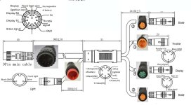

Where you found that 9-pin diagram, I searched the whole internet and not find it, only with 8-pin  Thanks.
Yes, I will double-check, and continuity from 9-pin to 3-pin to found correct 5+ pin.
If connect 2 sensors on the same 5v throttle wire, would be that enough voltage for all 3? (throttle+2 sensors).
Or I can leave just right side brake sensor.
What will you do?
Yes, I will double-check, and continuity from 9-pin to 3-pin to found correct 5+ pin.
Not sure what that means?If the brake sensors cannot be hooked in parallel, then thy shouldn't have sold them as a pair.
If connect 2 sensors on the same 5v throttle wire, would be that enough voltage for all 3? (throttle+2 sensors).
Or I can leave just right side brake sensor.
What will you do?
docw009
1 MW
I decided to buy the small 20A KT controller with Julet connectors. Only pswpower appears to have them. Everyone else sells the 17A. I was pleasantly surprised to see the wiring diagrams for the first time ever anywhere, but they were out of stock on the motor harness. So I get the controller in a few weeks. Only $28 for the controller, and $8 for two plastic controller cases, but it's $22 for shipping,
Those sensors have to work in parallel. You can connect them with the same power/ground and the signals common. One can be ON with the other OFF w/o affecting the signal. If they won't work in parallel, then the designers screwed up big time,.
Those sensors have to work in parallel. You can connect them with the same power/ground and the signals common. One can be ON with the other OFF w/o affecting the signal. If they won't work in parallel, then the designers screwed up big time,.
Mean your sensors?Those sensors have to work in parallel.
But my sensors not work?
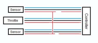
Why is working parallel important? Each of this brake sensors have own separate Signal wire. And 5v wire they share before that wire goes to throttle.
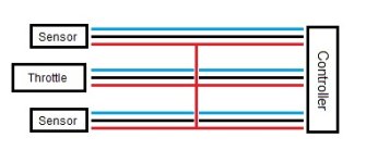
Inside the controller those wires all go to the same places. (all brake signals lead to the same brake signal sense input, all 5v to the same 5v source,all grounds to the same ground plane, etc).
If brake sensors can't be paralelled, then you can't use two on the same controller, so you can't have one on both brakes of a bicycle, or all three brakes of a tricycle, etc., so the controller would only ever be able to shut off it's power when the brake that it's sensor is attached to is used--if that brake is not used but another one is, the controller would not shut off, with whatever applicable consequences to the controller, motor, rider, etc.
All brake sensors I have ever seen can be paralleled, because they all simply use an open collector active=ground output, or a simple mechanical switch that grounds the output.
Even the controllers that use an active=high output use brake sensors/switches that work the same way, and can be paralleled with each other.
(you can't parallel an active high with an active low, but unless you have multimotor system using different controllers with different brake input types, this would never come up.)
AFAICT from the little info provided so far, the sensors are simply not being powered by the controller correctly, so they then can't operate correctly.
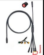
not been around.. think ive caught up..Let me just check this first: Are you aware that I have 2 separate brake sensor connectors?
View attachment 348457
EDIT:
I mean connect just red wires, that not will work?
Every sensor have own separate signal and ground wire going from controller to throttle.
View attachment 348458
We know your brake sensors need to ground the signal wire in order to cut off the motor as intended. (controller label)
you have confirmed the brake sensors work as expected with a battery.
A continuity test will confirm that both the signal connections in the 2 x harness sockets will both connect to the same controller input at the other end of the cable. ( if not backtrack further down the cable to the controller.) This IS how they work
Taking the same +5v from your cable to power the brake sensors will not be a problem. As if you trace back all +5v wires, they will trace back to the same controller +5v output and as such its safe to conclude it is intended to power ALL expected connected sensors etc.
as for the throttle, your above test provided a positive voltage close to 5v on the signal wire, I am unclear if this is a open or closed throttle reading? My understanding is the throttle output should be within a range of low to high voltage output
(+1v to +4v) ish.. low indicating low or zero throttle and high - full throttle.
No no. According to my post #24, the signal wire +3.8v tested on open jack from battery (not connected to throttle!).fill said:
I am unclear if this is a open or closed throttle reading?
Now again I tested for you all voltages on connected wires between battery->throttle.
Watch out. The test is used on PAS=0 ! That settings, I set that throttle not active. Throttle is active from PAS1-5. Don't know is that something to with this test, but when wheel rotate I can't measure
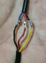
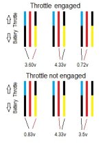
docw009
1 MW
I suggest you do it this way, as you don't know where the 3rd pin on the harness brake plug really goes, That way, you are not running the power line from the throttle to somewhere it shouldn't touch.
Per the PSWpower drawing, it shows the brake plug should have +5V, but if it's not there, who know knows what they did,
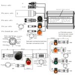

Per the PSWpower drawing, it shows the brake plug should have +5V, but if it's not there, who know knows what they did,

Last edited:
My New tests:
I tried looking where that third pin can be connected.
Tried 3-pin continuity of sensor connector with throttle connector, and only found Ground connected together.
Tried continuity of two same 3-pin sensor connectors, and two pins are connected, but the third mystery pin is not.
Tried also continuity of old harness cable 1T4, and can confirm that All 3-pins pins connected to back connector (8-pin from other side).
Let's back. Can you tell me (on 3-pin Sensor connector), why on my “signal” pin show 4.6v? This looks like a +5v pin... Shouldn't it be like +3v if is that signal?
**EDIT: TEXT DELETED**
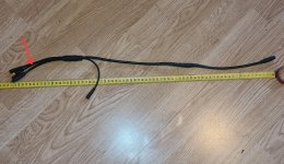
Also question is it wire, which go to
that mystery pin, maybe not connected good in middle of harness(where I shortened it)? But I don't think so. If is disconnected there in middle, I think that others +5 pins would also not work on other connectors.
I tried looking where that third pin can be connected.
Tried 3-pin continuity of sensor connector with throttle connector, and only found Ground connected together.
Tried continuity of two same 3-pin sensor connectors, and two pins are connected, but the third mystery pin is not.
Tried also continuity of old harness cable 1T4, and can confirm that All 3-pins pins connected to back connector (8-pin from other side).
Let's back. Can you tell me (on 3-pin Sensor connector), why on my “signal” pin show 4.6v? This looks like a +5v pin... Shouldn't it be like +3v if is that signal?
And second, your idea is very very good! Thanks!I suggest you do it this way, as you don't know where the 3rd pin on the harness brake plug really goes, That way, you are not running the power line from the throttle to somewhere it shouldn't touch.
View attachment 348593
**EDIT: TEXT DELETED**

Also question is it wire, which go to
that mystery pin, maybe not connected good in middle of harness(where I shortened it)? But I don't think so. If is disconnected there in middle, I think that others +5 pins would also not work on other connectors.
Last edited:
Ar
Just like the brake:low on the label there can also be an indicator to throttle/speed control expectations on a controller label too.
But if that is how its connected and its working when pas1-5 are engaged, yeah its showing a low signal (0.83v) when the throttle is closed and a high 3.6v when open.. as i would expect the 1-4v suggestion above was just a guesstimate not a cast iron prediction.. ( good job pas-0 lets you test..)
So looks good to me, though im only a couple of bike fixes further down the rd myself, far from expert..
Generally speaking How and when the throttle is engaged is usually configurable within the 'advanced' settings of your display. and for details of that you should refer to the manual for your bikes display unit. The settings you configure on a display unit are stored in the display unit and passed to the controller during the start up 'handshake' when you turn on the system.
Im still unclear 'open jack from the battery' are words? perhaps its a locally known idiom ?No no. According to my post #24, the signal wire +3.8v tested on open jack from battery (not connected to throttle!).
Now again I tested for you all voltages on connected wires between battery->throttle.
Watch out. The test is used on PAS=0 ! That settings, I set that throttle not active. Throttle is active from PAS1-5. Don't know is that something to with this test, but when wheel rotate I can't measure
View attachment 348554
View attachment 348555
Just like the brake:low on the label there can also be an indicator to throttle/speed control expectations on a controller label too.
But if that is how its connected and its working when pas1-5 are engaged, yeah its showing a low signal (0.83v) when the throttle is closed and a high 3.6v when open.. as i would expect the 1-4v suggestion above was just a guesstimate not a cast iron prediction.. ( good job pas-0 lets you test..)
So looks good to me, though im only a couple of bike fixes further down the rd myself, far from expert..
Generally speaking How and when the throttle is engaged is usually configurable within the 'advanced' settings of your display. and for details of that you should refer to the manual for your bikes display unit. The settings you configure on a display unit are stored in the display unit and passed to the controller during the start up 'handshake' when you turn on the system.
Sorry. I mean that was test (post #24) where wires from one side are connected to battery/controller and from other side not connected anywhere (open whire).Im still unclear 'open jack from the battery' are words? perhaps its a locally known idiom ?
And new test yesterday show that ends of wires connected to throttle (no open ends), like it must be.
EDIT:
Btw guys, when I was installed my temporary brake sensor (with glued magnet), I had no idea that 1 pin on harness not working! But that are 3-pin connector! So, it seems working only on two wire, and they sold them with 3-pin?
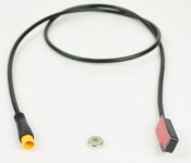
Last edited:
docw009
1 MW
You had the two wire magnet sensors working before? The new ones seem like more trouble than than they are worth. . I thought they used a 3 pin IC to replace the two pin magnetic switch.
I have no idea how they are supposed to work with your red lights. The light might mean it has power and it goes off when the switch is activated.
I have no idea how they are supposed to work with your red lights. The light might mean it has power and it goes off when the switch is activated.
No. Only had one istalled on right side. Other one is in package.You had the two wire magnet sensors working before?
Yes, exactly. But they are niceThe new ones seem like more trouble than than they are worth
And on old one sometimes I remove magnet with fingers and then not brake.
New sensor have same continuity on ground wire. Is it possible that is reason of both light in same time?
I can test both sensor with outside separate battery if that helps..
Yes. I checked again continuity of two 3-pin connectors for sensors. Both share same 2 pins (signal and ground) except third which not exist.if both sensors share the same +ve ground and signal wires, tripping one sensor is going to ground the signal wire from the sensor but also back feed that grounding to the 2nd un-triggered sensor too along its signal wire..
So, let say that all working fine.
Guys, please one more time.Amberwolf said:
You should have one that is the same 5V you can measure on the throttle connector that is the 5v power supply, another that is 0V that is ground, and a third that should be nearly 5v that is signal.
I had searching for tutorial, but nowhere find this situation.
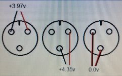
This is harness side, side from controller. Connector for throttle.
Which name of pin is there? How can I have +4v and +3v on the same upper right pin?
(color lines are my probe).
Is it Signal left and Ground at bottom?
How can be sure?
Last edited:
docw009
1 MW
Probing the throttle always is confusing, In your diagram, bottom center is ground. Top right is power. The signal pin will be top left, measured to ground, will be zero if nothing is connected. If measured relative to the power pin, it will be about 4 volts lower, as your measurements show.
I believe this is not in accordance with the diagram from pswpower. So much for their accuracy,
I believe this is not in accordance with the diagram from pswpower. So much for their accuracy,
Last edited:
Yes looks good,hope its as grand ride for youYes. I checked again continuity of two 3-pin connectors for sensors. Both share same 2 pins (signal and ground) except third which not exist.
So, let say that all working fine.
Thanks @docw009.Probing the throttle always is confusing, In your diagram, bottom center is ground. Top right is power. The signal pin will be top left, measured to ground, will be zero if nothing is connected. If measured relative to the power pin, it will be about 4 volts lower, as your measurements show.
I expected if I will have "+" on upper right Positive, then Signal wire will also show me "+" and will be separated, and because that (and lower voltage), I will know that is it signal for sure.
But in this case Signal have "+" on right side where is Positive, instead left on his own position🫨 Very confusing.
And if I reverse probe, red to the left (where signal must be), will be "-" on Signal position (-3.97v)
Similar threads
- Replies
- 37
- Views
- 1,325


