Series AC Induction Trike

Jason,
Thanks for sharing the build photos of your beautiful trike.
1. I notice that you plan to use Maxwell super capacitors. If you want I can send you a paper from MIT on using super capacitors for an electric go cart.
2. Is it possible to use a standard 1 HP AC motor and over power it to save weight instead of a 2 HP motor? Industrial motors are designed for contious duty with reserve capacity. You are probably not using the full potential of the 2 HP motor.

Don Gerhardt
 
Don - I'd be most grateful for the paper regarding the Ultracap go kart. I'll send you my email address in a PM.

Your second question/point is a great one. The service factor for this 2 hp motor is 1.15, but I estimate that running it (with higher currents) up to 150% (3 hp) for short periods of time would be no problem. In fact, my controller is rated for 3 hp and can provide these types of power levels if necessary, though the inverter is only rated for 1500 W (2 hp).

The real reason I decided on 2 hp rather than sticking with 1 hp (my old motor) was torque. An induction motor of this style is rated for around 3 ft-lb of torque per horsepower, which translates to about 4.5 ft-lb at locked rotor (stopped) conditions. I required at least 6 ft-lbs rated (9 locked rotor) to achieve around 50 ft-lbs at the rear wheel's center to get the right acceleration and hill climbing after gearing down.

It's easy to run the motor at higher than its rated power for a certain period of time, but getting enough torque for acceptable acceleration is not as simple of a task. That said, with my present transmission, you could still find a way to live with a 1-hp motor. It would still weigh around 33 lbs, though.

Best,
Jason
 
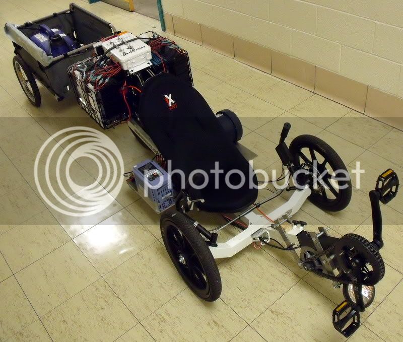
I think it's time to make another update on the AC Trike, which I am now referring to as "The Monstrosity." You'll see what I mean.

I hooked things up just like I'd intended in one of my previous posts, which was (in terms of a power pathway):

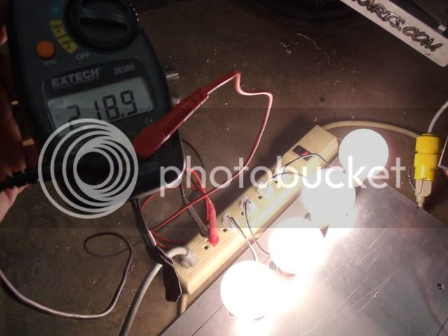
Generator --> 15 V power supply --> 990 F, 15 V Ultracaps --> Inverter, 15 VDC to 220 VAC (modified sine wave) --> AC variable frequency drive --> 3 phase AC motor

Two major problems arose: first, the original 15 V power supply, rated at 645 W, had constant current overload protection which attempted to throw around 55 A into the caps until they were very nearly full charge. This threw the generator (1 kW peak) into overload, its engine slowed down, output voltage and current dropped. Once this happened, the generator never recovered, switching off after a few seconds. After trying a lot of dumb workarounds, I gave up and got a similar unit which was rated at 480 W, and it provided a manageable (for the generator, anyway) constant overload current of 45 A, which will not cause a generator shutdown. The second problem was the inverter. It is rated for 1500 W and this is fine for most cruising you'd try to do. But, unfortunately if you draw even just a slight amount more than its rated 6.8 A - even for a fraction of a second, it shuts down and requires an off/on cycle. Very annoying, especially when it happens on a hill. I tried to program an appropriate current limit into the motor drive, but it was not 100% reliable. So, I thought again about rhitee's earlier comment.

rhitee05 said:
Running DC directly to the controller would remove two stages, since the controller internally rectifies to DC then re-inverts to AC (the data sheet you posted shows this). Getting 220VDC would be trickier, but still doable. Running a high-voltage DC bus has the added advantage of lower currents, thus lower losses and thinner wires needed.

Assembling a 200 VDC capacitor pack would be cost prohibitive, but using SLA batteries the same way would not. If I chose batteries small enough, I could get a 200+V pack without it weighing a ton. The goal was to allow the inverter to supply power as it could, but if its draw became excessive, the batteries could feed energy into the motor controller's DC bus (and also be "float charged" by the DC bus when the inverter was not overstressed). I couldn't feel safe using any other battery chemistry without a BMS of some type, and SLAs have a good tolerance for float charging in series. The new strategy, overall:

[pre]Generator --> 15 VDC power supply --> 330 F, 15 V Ultracap --> Inverter --> AC VFD --> 3 phase AC motor
250 V Battery Pack <--|[/pre]

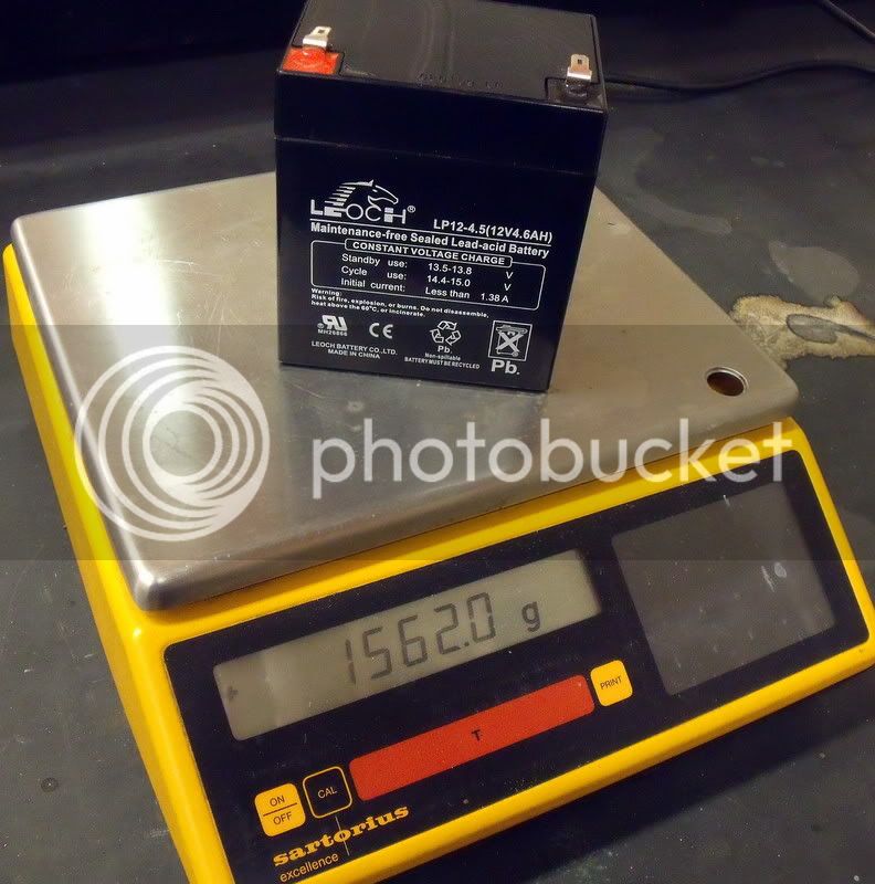
The first step was to purchase enough SLAs to make the right sized bank. The motor controller requires a DC bus voltage between 195 V and 395 V DC to avoid under- and over-voltage trips. When powered using the inverter's 220 VAC input, the bus would rest at around 250 VDC. The recommended float charge potential for SLAs is 13.5 V per battery, so I'd require 19 batteries to be within the safe float charging regime. I decided on Leoch 4.5 Ah SLAs, which weigh about three and a half pounds each.

LP12-45_mass.jpg


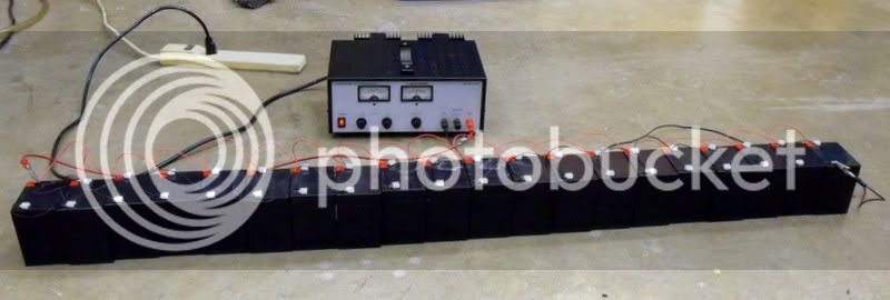
To get all the SLAs charged and balanced after receipt, I connected them in series and float charged at 13.5 V for a couple of days.

chg_parallel.jpg


I had planned on charging them in parallel like this once, then connecting them in series:

8_series.jpg


However, I didn't look forward to figuring some awkward and probably unsafe way of getting them back to parallel every now and then to make sure that they were balanced. Somewhere on this forum I read about using double throw switches to make series/parallel connections, and I proceeded to take the idea to a ridiculous level of complexity.

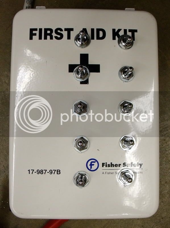
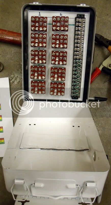
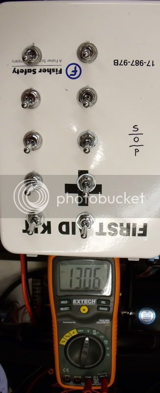
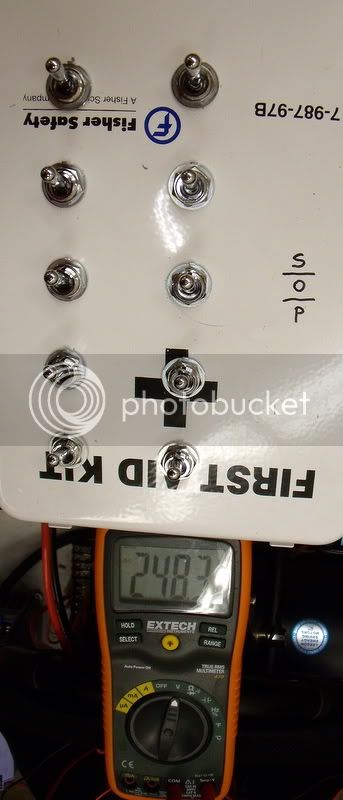
Something about this first aid kit looks a bit strange...

FAK_Switches_Top.jpg


I used it as an enclosure for a total of ten four pole, double throw (4P2T) switches; although I really only needed nine for nineteen batteries. Here is the box before wiring:

FAK_Prewiring.jpg


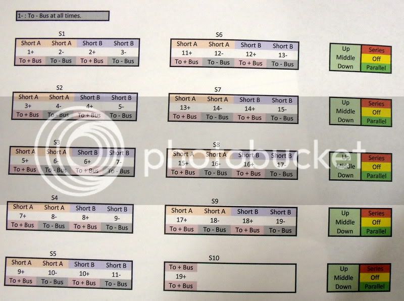
The switches were three position "on-off-on," where the middle "off" position was absolutely critical during switching. The idea was to follow a certain pattern for battery wiring to allow "series-off-parallel" wiring.

4P2T_Scheme.jpg


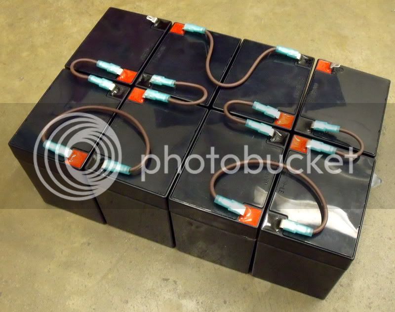
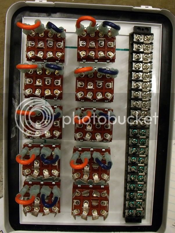
Things weren't too bad with the shorts wired,

FAK_Shorts.jpg


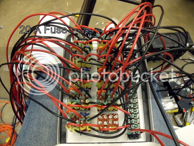
But things quickly got more complicated and space ran short. Here's the completed wiring inside of the box. The 20 A fuse is in the series circuit, of course.

FAK_Completed_Interior.jpg


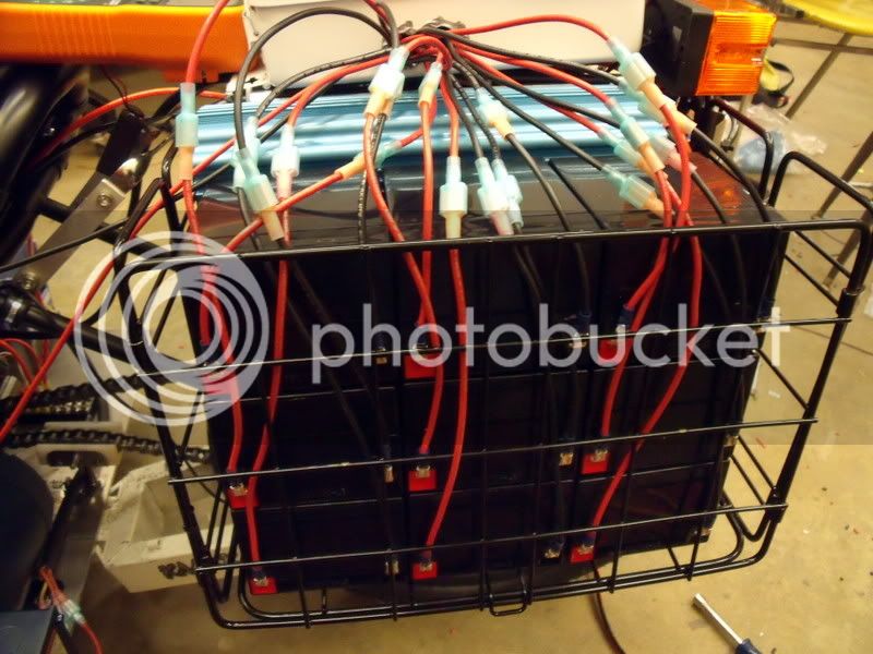
It took a few days for my fingertips to recover from all the wire twisting, crimping, and pushing the quick disconnects. A couple of holes were punched in each side of the first aid kit, and the wires were run out to the side racks, which now held the batteries. Here's the left side:
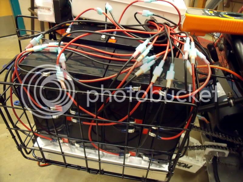
LH_Basket.jpg


And the right.

RH_Basket.jpg


More quick disconnects here allow me to remove things from the racks as needed. When all the switches face the front of the trike, the batteries are in parallel.

Parallel_Volts.jpg


Turning all of the switches off, and then towards the back of the trike, we have a series connection.

Series_Volts.jpg


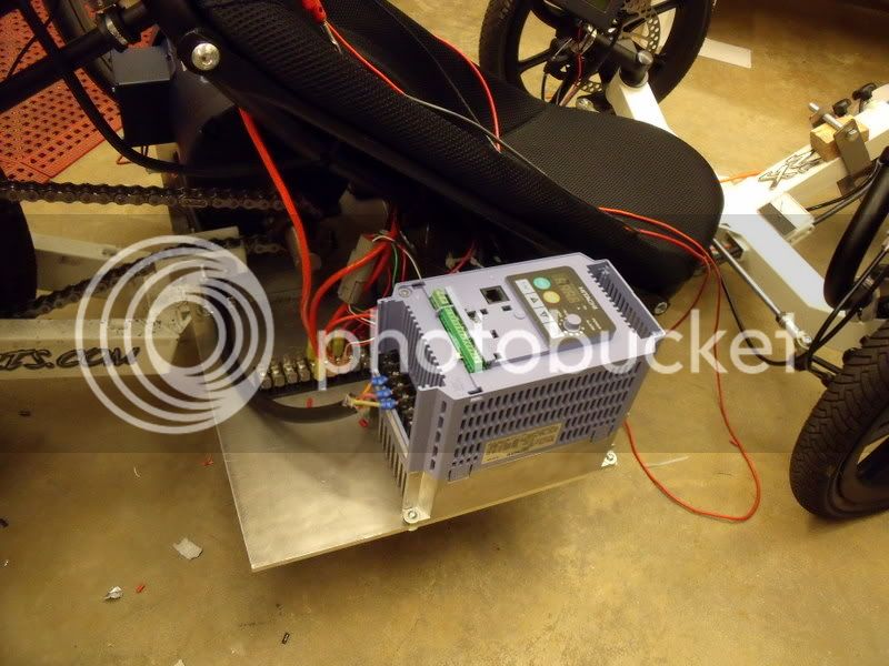
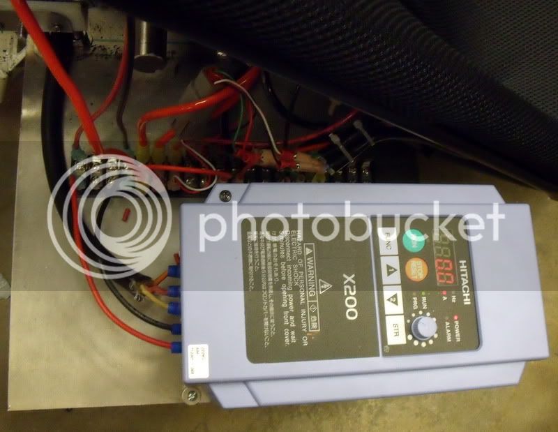
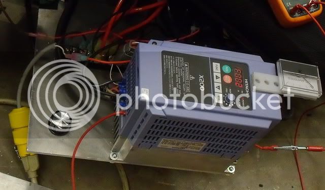
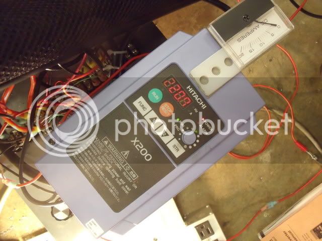
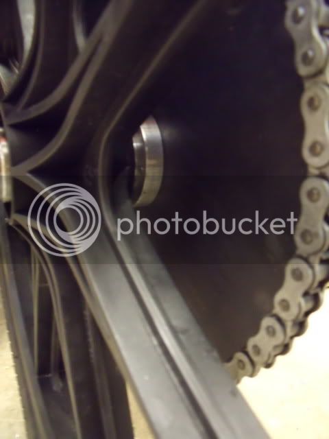
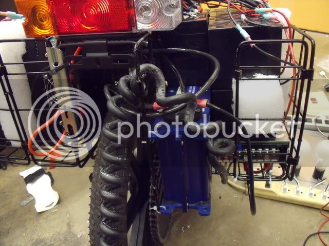
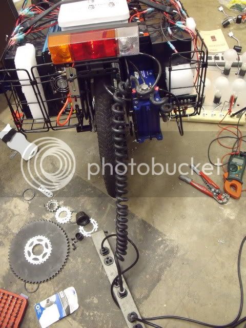
The extra space taken up by the batteries required mounting the motor controller up front. This is a good thing, in that now I can use the built-in speed dial and also have ready access to the stop button (used as a kill switch), and can monitor motor current or frequency just by looking down at the display.

Hitachi_Mounted.jpg


The motor phase wires are connected as before, and I used the batteries in a direct connection to the DC bus to test with the controller (no AC input).

HVDC_Bus.jpg


Hitachi_Running_Batteries.jpg


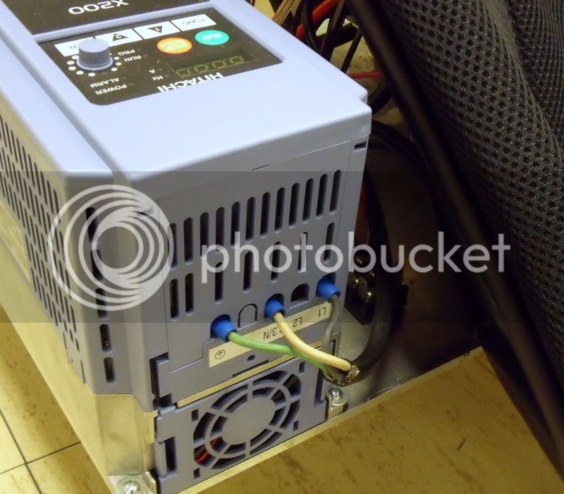
The inverter is connected to the 1-phase AC input terminals on the controller, and it powers up the DC bus to over 250 V when running normally.

Hitachi_1Ph220VAC_Feed.jpg


DC_Bus_Inverter_Only.jpg


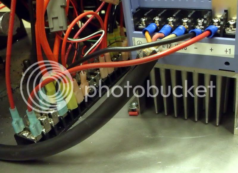
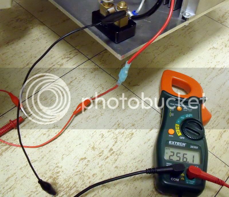
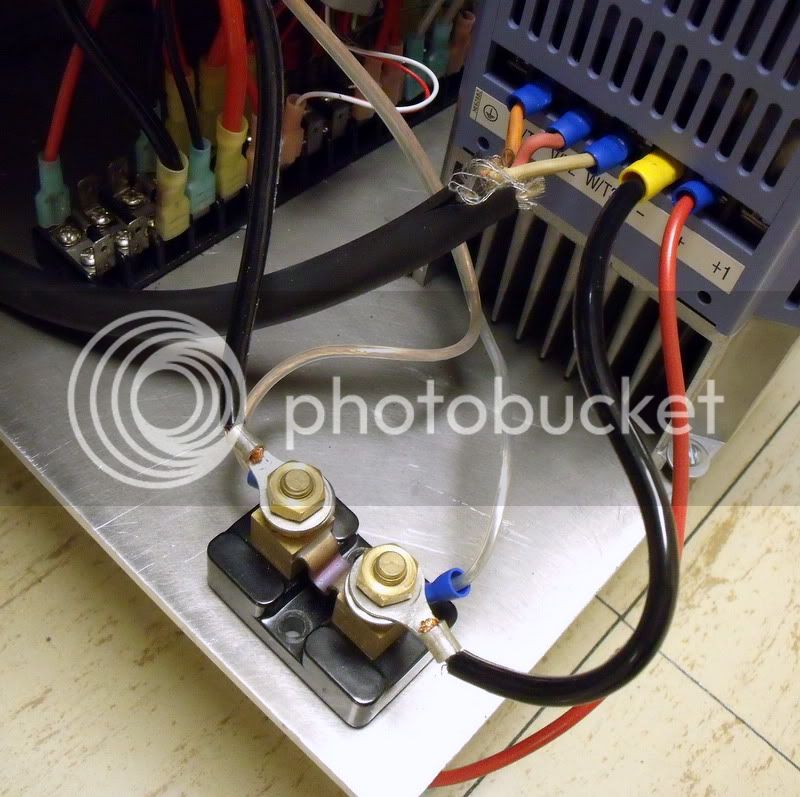
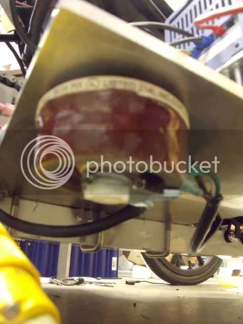
I re-installed the shunt resistor on the negative high voltage DC bus, but I may get rid of it as it's giving me shaky readings. Here you can see it with the positive line disconnected.

Shunt_Resistor_Mounted.jpg


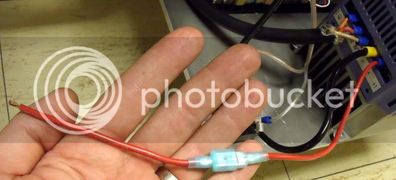
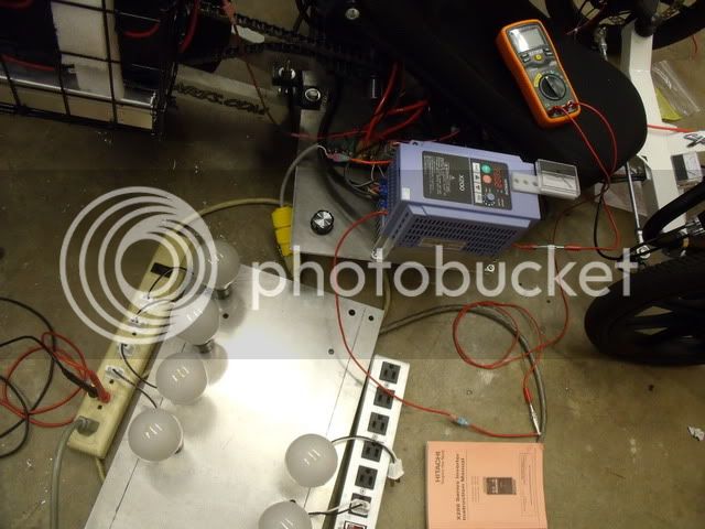
In fact, the positive line is always disconnected unless I'm driving, for safety. Also, when powering up the controller using the batteries (no inverter power), I use a "sparker" or sacrificial wire to make sure that the controller's inrush doesn't create an internal spark to destroy the switches.

Sparker.jpg


Once the controller's caps are charged, I disconnect the sparker and connect the positive HVDC line to the terminal strip. Here's the overall trike, with the generator-trailer attached.

Overall_Rear.jpg


Overall_Front.jpg


:!: One note I'd like to make to anyone considering multiple voltage buses on their vehicle: make sure to connect every unit to the same chassis ground! My 250 VDC and 15 VDC buses share a common negative chassis ground, and the AC power delivery systems (generator, inverter) are also grounded to this unified negative bus. Do this, and you'll save time & money (and won't risk a fire). :!:

So far, it looks like this system (while ugly) works pretty well. I can leave the trailer behind, leave the inverter powered down, and use only the batteries to get around - charging them in parallel when I'm done. Maybe best of all is that the higher voltage causes each battery to deliver relatively little current, so that they might actually deliver a decent percentage of their rated capacity. That's important, since if I could squeeze at least 3.5 Ah out of these 4.5 Ah batteries, I would expect a total usable energy of around 800 Wh for this pack. For longer trips, I can hook on the trailer and generate electricity as I go (the real long-term goal: cross country cruiser). I'll be doing some test drives tomorrow if I can - should be fun.
 
I have been following with great enthusiasm this thread as I believe it has a lot of merit. I just have the hunch that JCGs "lurch into lead" is the wrong way to go. I am not up to doing the maths and haven't the knowledge to suggest the way that this should go. To use ultracaps as a buffer between generator and drive seems a great idea. If hill climbing is more demanding than the ultracap capacity is capable of supplying (insufficient buffer storage) then LiFePO4 would seem a better way to go, as it is capable of such high discharge/charge rates and is much lighter. What do you think?
 
Hi Paul - I'm glad you're enjoying the story of Frankenstein's Trike! Of course you're right, the use of SLAs here is a great compromise; what I'd rather do to further my own understanding of future work with an electric car's 300+ VDC system would have been to install and use a large bank of ultracaps, but the smallest ones so that it wouldn't take up too much space. Much more interesting would have been to buy 100 of these and connect them in series, while having them charged by (and discharged into) the controller's DC bus:

25 F, 2.7 V

Although that would cost about $550 USD and would be very difficult for me to make into a module with all of those pin connections. One (probably solvable) problem would be how to provide enough current to charge the capacitors from an initially dead state, which neither the inverter nor the controller can handle. It would also be only about 7 kJ of usable energy (for 50% discharge)... the scale of this trike's power-to-weight ratio hurts the idea of a large cap buffer that would also be small enough to fit onboard (or to be affordable for purchase). I believe the ratio for a full-size vehicle makes much more sense, but that's another discussion.

If a battery is to be used, I would be concerned about connecting a large series of batteries with any other chemistry than lead acid to the controller's DC bus, with the main fear being overcharging. I haven't seen any previous work with reliable reports for float charging Li or Ni cells in the same way that Pb may be. Also, the battery management would become a great deal more complicated and would require the use of a special charger.

I don't think that there are any NiMH/LiPo/LiFePO4 packs being used by people here with such an excessively high voltage... but if there are, maybe they could share insight on how they manage multiple packs or around 75 cells connected in series.
 
I am not sure if there are any packs that high a voltage here, but you might check out DIY Electric Car forums. I think there are a couple of builds in the garage there or in threads that are pretty high-voltage AC designs. I'm sorry I can't remember the names though.
 
Time for another quick update. My wife and I took the trike out for some track tests a few weeks ago in an attempt to gather info related to power draws to the motor at different speeds on flat ground. Things were going well until we started racing around the track at very high speeds, when I noticed that the 15 V capacitor was discharging, and the inverter eventually tripped as its supply voltage dropped below 10.5 V. The trike continued operating on battery-only power, but this wasn't the way it was intended to operate.

I had expected, perhaps foolishly, that the output voltage of the inverter would drop as its feed voltage dropped, and that the result would be a drop in the voltage of the controller's DC bus. That would allow the batteries to take over as needed. Instead, the inverter did whatever it needed to do in order to keep its voltage constant - which was at a higher value (252 VDC or so after rectification) than the battery pack (around 240 VDC at rest). As a result, the motor controller pulled power from the inverter until it turned off, then switched to the batteries.

I needed a way to make the inverter's voltage output decrease as the power (or current) output from it increased, so that it was limited to a total power delivery of around 400 W, which is deliverable at steady state by the 15 V power supply that charges the capacitor. For this, I installed a rheostat (75 W, 0-200 ohm). I mounted it in the support plate, so that the dial is accessible. The rheostat runs on the AC line from the inverter.

DSCF1421-1.jpg

DSCF1428.jpg


To test its affect on the DC bus voltage as a function of power delivery, I used a bank of 100 W light bulbs (250 V versions) connected in parallel using a couple of power strips.

DSCF1421.jpg


In this example, setting the rheostat to around 25 ohms and using four lights I measured a DC bus voltage of 219 V and the lights passed a current of around 1.4 A. That's a 300 W or so draw, 350 W including the power dissipated by the rheostat, and the capacitor charge was maintained by the power supply.

DSCF1423.jpg

DSCF1424.jpg


So, you can imagine that for that particular resistance setting, the batteries would kick in before the bus voltage would drop all the way to 219 V. Setting it properly allows me to both set a maximum delivery power for the inverter, and a maximum discharge voltage for the battery pack. When the trike comes to rest, the bus voltage rises to 250 V or so and float charges the battery. Obviously, the sooner that the batteries kick in to help out, the less power gets wasted in the rheostat.

I have also found a way to monitor the bus voltage using the controller display, which gives me a concept of how the system is working while operating.

DSCF1425.jpg


Other improvements: the bike now has regen - I have removed the freewheel and have put a 60-tooth sprocket directly on the disk brake ring.

DSCF1419.jpg

DSCF1420.jpg


Finally, I've got a telephone-cord style plug that'll go back to the generator. Should be a bit more suitable for swinging back and forth with the trailer.

DSCF1418.jpg

DSCF1417.jpg
 
Great stuff, JCG. Have you some stats on the speed, endurance (range) etc on the trike that you can share? Even video of a trip. BTW is there possibly another strategy for controlling the bus voltage that doesn't involve wasteing 50 watts in a rheostat? What you need is control of which power source the juice is coming from: battery or ultracap. Not up to your level of knowledge on electrics though, so that might be a silly suggestion.
 
Please don't take this as a negative. I am not trying to criticize and I realize this is a large rolling experiment. However, this thing has ALOT of large, heavy equipment on it. Is all of that really necessary? Again, I am not trying to insult this project. I really can appreciate how much time went into it (plus, I love KMX stuff :D 
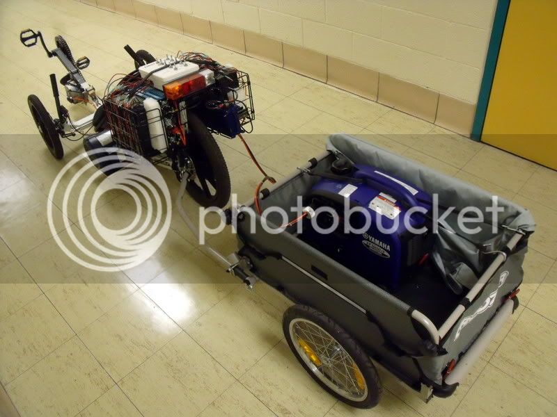
). I just cannot get over how much equipment is being lugged around. :shock:

What is your WH per mile on this?

Oh, I love the series hybrid thing, though. I believe that may be the wave of the future in certain respects.

Matt
 
Hi Matt, I've only got "around the track" data at the moment, and a couple of approx. 1/10 mile runs up and down a gentle hill (haven't taken it on a trip to & from work yet, but will in the spring). From the track data, the most recent configurations had about 20 Wh/mi with batteries only (no trailer) and 23 Wh/mi with the trailer (and its generator) at practical cruising speeds similar to my speeds in the city on my regular bike (say 15-18 mph). It is pretty heavy but not unmanageable, and if it's built to go long distances the weight and regen are less important.

But really, the main value I'm getting out of this is seeing stuff I didn't expect and working through the problems, like the generator overloading or the domination of the delivered power by the inverter, etc. It's felt pretty rewarding to do everything in troubleshooting style up to now. The whole thing is heavier than the ideal, but it's a system I feel comfortable tweaking and should be pretty solid in the field (knock on wood).

Paul, this rheostat function would be better accomplished with some kind of transformer that could deliver a different voltage based on its current delivered, something with some simple control circuit that I guess would boil down to current control. If dimmers cut out at a higher potential instead of turning on, I would have gone with something like that. But the power loss is kept pretty low as long as the batteries are not too discharged (which would force the inverter to work harder at higher currents). There's definitely a better way to do it but I don't know enough to build a control circuit like that on my own. I'll just have to wing it with stuff like the rheostat, unless there is a simpler way I'm overlooking (but I'm always fishing for that kind of advice here).

Can't wait for another chance to get this thing out and about!
 
JCG said:
Paul, this rheostat function would be better accomplished with some kind of transformer that could deliver a different voltage based on its current delivered, something with some simple control circuit that I guess would boil down to current control. If dimmers cut out at a higher potential instead of turning on, I would have gone with something like that. But the power loss is kept pretty low as long as the batteries are not too discharged (which would force the inverter to work harder at higher currents). There's definitely a better way to do it but I don't know enough to build a control circuit like that on my own. I'll just have to wing it with stuff like the rheostat, unless there is a simpler way I'm overlooking (but I'm always fishing for that kind of advice here).
Well, what is the sphere for! Come on chaps (GGoodwin, Fechter, you other electronics wizards) help JCG out here! Challenge: How to integrate battery and ultracapacitor power for a KMX trike. If you don't respond I might have to make a new thread called that! :D
 
Right on Paul - the concept of current control from an AC source would be not only useful here for this project but would really help out with other stuff that's looming on the horizon... eventually I want to deal with charging a lot of caps from a generator. I've read about power losses being worse when done at constant voltage rather than constant current... get most generators are run with voltage regulation but no current control. Maybe it's easy to do...?
 
JCG said:
Hi Matt, I've only got "around the track" data at the moment, and a couple of approx. 1/10 mile runs up and down a gentle hill (haven't taken it on a trip to & from work yet, but will in the spring). From the track data, the most recent configurations had about 20 Wh/mi with batteries only (no trailer) and 23 Wh/mi with the trailer (and its generator) at practical cruising speeds similar to my speeds in the city on my regular bike (say 15-18 mph). It is pretty heavy but not unmanageable, and if it's built to go long distances the weight and regen are less important.

But really, the main value I'm getting out of this is seeing stuff I didn't expect and working through the problems, like the generator overloading or the domination of the delivered power by the inverter, etc. It's felt pretty rewarding to do everything in troubleshooting style up to now. The whole thing is heavier than the ideal, but it's a system I feel comfortable tweaking and should be pretty solid in the field (knock on wood).

Can't wait for another chance to get this thing out and about!

Gotcha.

Again, I like the project. I was merely curious about the amount of stuff on it.

At any rate, I agree with you about the R&D thing. I love debugging and working out cool details that would otherwise not be visible without simply building and running something.

Matt
 
Back
Top