
You are using an out of date browser. It may not display this or other websites correctly.
You should upgrade or use an alternative browser.
You should upgrade or use an alternative browser.
Speed controller design (Based on arlo's Game Changer)
- Thread starter trialspower2
- Start date
trialspower2
100 W
- Joined
- Dec 31, 2016
- Messages
- 108
That is not something I have come across before, but sounds interesting. I know the PIC chip can deal with dead time, but I would have to look into how to produce the complimentary PWM signal on the correct phase. I am fairly sure its possible though as each PWM output has its own period register.
Doctorbass
100 GW
subscribed!
Nice work btw!
Doc
Nice work btw!
Doc
trialspower2
100 W
- Joined
- Dec 31, 2016
- Messages
- 108
little update,
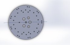
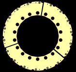
I have now changed the drivers to ISO5852S so that I can have desat protection. I have split the control board into two layers. The first layer is the driver board, which can be seen attached. The second layer will contain the microcontroller and all the inputs/ outputs. The driver layer has 3 ISO5852s mounted on each side, and 6 isolated DC-DC converters.
I am finding it difficult to work with the circular layout on Diptrace, however I have come up with a layout never the less. I have tried to keep all transistors the same distance from the driver chip as much as possible.
Now that I need to bring each phase output, bus+ and bus - to this board for the desat, it going to make putting together all the layers even more difficult. My plan is to put M1.6 studs into the plates as I am building the layers. Once all complete I will then solider them into the driver board along with all the FET gates. This does however mean splitting it apart again will not be easy. I was thinking if I make the holes for all these connection on the large side, it might be possible to desoldier if one using a basic soldier sucker.
Attachments

Animalector
10 kW
I started using vertical connections between boards but have abandoned it for edge mount connections it's just not practical to build and near impossible to service. I am really liking the symmetry of the layout. No idea if it's good or bad, but I like the concept / look of it.
I want to point out my opinion I don't think the control or the digital should be in the middle.
I think the middle of something like this will have large magnetic forces. My next Version of game changer has the controls on the out side 90deg to the driver boards.
I think the middle of something like this will have large magnetic forces. My next Version of game changer has the controls on the out side 90deg to the driver boards.
trialspower2
100 W
- Joined
- Dec 31, 2016
- Messages
- 108
I could include a layer of steel between the output phase plate and the driver board, I think this would do a decent job at blocking the board from magnetic fields. I felt like the switching would be better if the drivers were as close to the FET's as possible and at a similar distance, but then I suppose as ever improving one aspect affects another and the success is knowing which things are most important.
marcos
1 kW
- Joined
- Nov 19, 2016
- Messages
- 348
You should install this between the seats with a big flux capacitor label.
Check the voltage rating of those smd resistors next to the power transistors, I'm not sure if they are 0603 or 0805, and not sure if those stand your dc link voltage + overshoots.
Remember to add schottkys from the gate line to vee+ and vee-. Arlo had a latchup issue and its schottky solution was a valuable lesson for all of us, these are expensive blows. Maybe its not needed for this power level, but its certainly a cheap protection.
marcos said:You should install this between the seats with a big flux capacitor label.
Check the voltage rating of those smd resistors next to the power transistors, I'm not sure if they are 0603 or 0805, and not sure if those stand your dc link voltage + overshoots.
Remember to add schottkys from the gate line to vee+ and vee-. Arlo had a latchup issue and its schottky solution was a valuable lesson for all of us, these are expensive blows. Maybe its not needed for this power level, but its certainly a cheap protection.
The schottkys were needed but the latchup was because the data sheet shows a 100ohm resistor for current limiting when it needs to be 1000ohms.
trialspower2
100 W
- Joined
- Dec 31, 2016
- Messages
- 108
You should install this between the seats with a big flux capacitor label.
I take it by this you don't think the steel plate would have a benefit? If it does become a flux capacitor that would be handy as I can install it in my celica supra, as it kinda looks like an delorean!
I will add the schottky diodes in for good measure. The resistors are 0805, with a working voltage of 150V, I will change these to 1206 for a working voltage of 200V, I am looking at running the controller up to 120V max.
trialspower2
100 W
- Joined
- Dec 31, 2016
- Messages
- 108
Another update,
Besides the main CPU board, I have got all the PCB's about finished for all the intermediate layers. I have also got the aluminium plates finishes with all the necessary holes for fixings and to clear the through hole components sticking out the back of the intermediate circuit boards.
I have a feeling that its going to be quite a challenge assembling it all in the right order. My aim is to get these PCB's on order and then layout the main board while I am waiting for them to arrive. I will also get the aluminium plates laser cut.
I have added a couple of large TVS diodes across the battery input, to prevent the FET's getting over voltage spikes should the battery supply start ringing.
I have tried to upload everything in the assembly order.
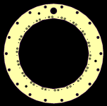
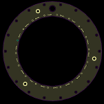
Attachments
-
 ground connection plate.JPG30.3 KB · Views: 830
 -
 negative plate.JPG41.7 KB · Views: 830
 -
 positive plate.JPG30.7 KB · Views: 830
 -
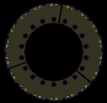
 negative PCB bottom.png7.8 KB · Views: 1,531
 -
 negative PCB top.png7.7 KB · Views: 1,531
 -
 positive PCB bottom.png10 KB · Views: 1,531
 -
 positive PCB top.png9.4 KB · Views: 1,531
 -
 phase plate.JPG39.4 KB · Views: 830
 -
 steel shield plate.JPG24.3 KB · Views: 830
 -
 driver board bottom.png20.7 KB · Views: 1,531
 -
 driver board top.png22.5 KB · Views: 1,531
trialspower2
100 W
- Joined
- Dec 31, 2016
- Messages
- 108
Hello,
Its been a while since my last update, but I am pleased to say that the controller is now built and running.
With regard to performance I am still a little unsure as something does not seem quite right. I have been testing the controller by driving a 25kw 100v motor on 24 volts. I do not have a very good scope, but I am finding that the battery supply is rock steady while the motor is running and the switching of the transistors looks good when running at 100khz frequency. I am applying pwm to the low side only at the moment with the high side on.
What I am finding though is that the motor is using a lot of no load current, tripping a 10A fuse at about 65% throttle. These currents can be confirmed when clipping the battery cable. When clipping a motor phase, when the motor is turning slowly at around 1RPM my clamp meter is reading about 3A on AC current. Soon as I start to accelerate the motor this climbs quickly reaching 50amps by the time we are seeing 10A on the battery. I also noticed that the ring connects between the motor wires and the speed controller were getting hot! The controller also started to warm up quite quickly, as did the motor.
I have a current clamp plug in module for a multimeter, so I put my scope on this and I see a large spike in current each time the phase sequence changes. However these spikes are not evenly spaced. This got me thinking, what about the motor sensors. So I scoped these, and ideally a 3 channel scope would be the tool of choice, but with only a 2 channel scope I could still see quite clearly that the sensor pulses are not evenly spaced.
I then added a delay into the software between each sensor event, to delay the switching sequence, giving a period with all phases switched off. From this I found that when a phase is switched high for two changes of sensor event, the gap that appears between them which should split the switched on time in the middle, was only half the size at one side compared to the other, maybe even a 1/3rd of the size.
So it would appear to me that the motor sensors are the issue, however I would be grateful for any feedback. Unfortunately I only have this motor so I cant try a different one.
My plan is to make a flywheel for the motor for testing with slots in it for doing the feedback, but I am not yet sure how to make it for an out runner motor which seems to have 24 slots and 28 magnets after a quick count up.
Some pictures, I do have a video but can't upload it on here;


View attachment 2


Its been a while since my last update, but I am pleased to say that the controller is now built and running.
With regard to performance I am still a little unsure as something does not seem quite right. I have been testing the controller by driving a 25kw 100v motor on 24 volts. I do not have a very good scope, but I am finding that the battery supply is rock steady while the motor is running and the switching of the transistors looks good when running at 100khz frequency. I am applying pwm to the low side only at the moment with the high side on.
What I am finding though is that the motor is using a lot of no load current, tripping a 10A fuse at about 65% throttle. These currents can be confirmed when clipping the battery cable. When clipping a motor phase, when the motor is turning slowly at around 1RPM my clamp meter is reading about 3A on AC current. Soon as I start to accelerate the motor this climbs quickly reaching 50amps by the time we are seeing 10A on the battery. I also noticed that the ring connects between the motor wires and the speed controller were getting hot! The controller also started to warm up quite quickly, as did the motor.
I have a current clamp plug in module for a multimeter, so I put my scope on this and I see a large spike in current each time the phase sequence changes. However these spikes are not evenly spaced. This got me thinking, what about the motor sensors. So I scoped these, and ideally a 3 channel scope would be the tool of choice, but with only a 2 channel scope I could still see quite clearly that the sensor pulses are not evenly spaced.
I then added a delay into the software between each sensor event, to delay the switching sequence, giving a period with all phases switched off. From this I found that when a phase is switched high for two changes of sensor event, the gap that appears between them which should split the switched on time in the middle, was only half the size at one side compared to the other, maybe even a 1/3rd of the size.
So it would appear to me that the motor sensors are the issue, however I would be grateful for any feedback. Unfortunately I only have this motor so I cant try a different one.
My plan is to make a flywheel for the motor for testing with slots in it for doing the feedback, but I am not yet sure how to make it for an out runner motor which seems to have 24 slots and 28 magnets after a quick count up.
Some pictures, I do have a video but can't upload it on here;
View attachment 2
Doctorbass
100 GW
WOW! 
Electrofantasmic!
:lol:
Doc
Electrofantasmic!
:lol:
Doc
trialspower2
100 W
- Joined
- Dec 31, 2016
- Messages
- 108
Following my previous update where I was suspecting that the motor hall sensors were not good enough I decided to get a couple of large diameter disc laser cut to use for the sensors and to load the motor for testing. The larger top disc with sensor slots is 600mm in diameter and they weight 20kg so its a good amount of load to test the motor against.
Up to now I have only completed testing with a limited power supply, in the video I am trying to keep the current under 10A as I did not want the 10A c fuse to trip off.
Unfortunately my scope does not have a high enough sample rate, but it does give some idea of what is going on. The purple channel is battery voltage and the white channel is on one of the phases. Its a 50KV motor so I guess it reaches 1200 RPM. The no load current seemed about 6A, however there will be alot of drag from the slotted disc I would think.
If there is one thing I have learned it is the importance of correct sensor spacing. It makes a huge difference.
After running it for about 10 minutes the speed controller was still cold and there was a slight head build up in the motor.
I have purchased a 200A inline fuse, so my next plan is to get a couple of car batteries and some thicker wiring on it. I was thinking if I can measure the time it takes to spin the disc up to 1200RPM I will get an idea of power output?
Anyone any suggestion on how to calculate this?
Video links
https://youtu.be/nkuAbyYBLDA
https://youtu.be/DArXyrVBHxQ
trialspower2
100 W
- Joined
- Dec 31, 2016
- Messages
- 108
I managed to get 10 batteries together to test the controller under some load. I managed to get almost 200A when accelerating the flywheel about around 400rpm I guess. If I gave it full throttle from stopped the batteries could not provide enough current and it pulled the voltage down to 18V causing it to cut out before my meter could get any current reading.
I believe this is a 25kW motor on 100V, however am I right in thinking that if at 25v I get 200A and 5kW, at 50 volts I could expect 400A and 20kW? Is this normal? Do I need current limiting at lower RPM's?

I believe this is a 25kW motor on 100V, however am I right in thinking that if at 25v I get 200A and 5kW, at 50 volts I could expect 400A and 20kW? Is this normal? Do I need current limiting at lower RPM's?
Similar threads
- Replies
- 6
- Views
- 854
- Replies
- 3
- Views
- 869
- Replies
- 3
- Views
- 906